30
ENGF-107 REV. A 01/11
© 2011 AXEON Water Technologies
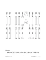
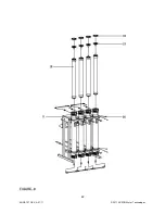
1. Remove one membrane element at a time from the membrane element
housings, from the top of the housing. Long nose pliers may be necessary to pull
the old membrane element out of the membrane element housing.
2. Lubricate the brine seal with non petroleum based lubricant, Silicone DC 111.
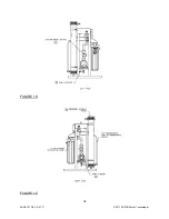
3. Install the brine seal side of the membrane element first (Figure 4, Page 30).
When the housings have a direction of flow from bottom to top, the brine seal
should be located at the bottom of the housing.
4. At a slight angle insert the membrane while slightly rotating the element being
careful not to tear or flip the brine seal. A slow twisting motion should be used to
insert the membrane element, to ensure the brine seal stays in place. Re-lube
the brine seal if necessary.
5. With a smooth and constant motion, push the membrane element into the
housing so the brine seal enters the housing without coming out of the brine seal
groove.
6. Re-install the end caps by gently twisting the end cap while pushing it onto the
housing. Ensure that you do not pinch or fatigue any O-rings while re-installing
the end plug. Push the end plug on until the outer diameter of the plug is flush
with the outer diameter of the membrane housing.
7. Insert the snap ring until it is fully seated. Install the locking clip if available.
8. Reconnect any fittings that may have been disconnected when the membrane
element housings were disassembled.
9. To Start-Up the system, please refer to the Initial Start-Up section of this manual.
(See Page 23)
CAUTION: WET MEMBRANES ARE SHIPPED IN A PRESERVATIVE
SOLUTION. THE MEMBRANES MUST BE FLUSHED FOR AT LEAST 1 HOUR TO
REMOVE THE PRESERVATIVE FROM THE MEMBRANE. DISCARD ALL OF THE
PERMEATE AND CONCENTRATE, WHICH IS PRODUCED DURING THE FLUSH
PERIOD.
Содержание CT-4000
Страница 1: ...Reverse Osmosis User s Manual Model CT 4000 CT 5000 CT 7000 CT 7000 Pictured...
Страница 2: ...2 ENGF 107 REV A 01 11 2011 AXEON Water Technologies This Page Left Blank...
Страница 10: ...10 ENGF 107 REV A 01 11 2011 AXEON Water Technologies HF1 STANDARD...
Страница 11: ...11 ENGF 107 REV A 01 11 2011 AXEON Water Technologies HF4 OPTIONAL...
Страница 12: ...12 ENGF 107 REV A 01 11 2011 AXEON Water Technologies HF5 OPTIONAL...
Страница 13: ...13 ENGF 107 REV A 01 11 2011 AXEON Water Technologies NF3 OPTIONAL...
Страница 14: ...14 ENGF 107 REV A 01 11 2011 AXEON Water Technologies NF4 OPTIONAL...
Страница 15: ...15 ENGF 107 REV A 01 11 2011 AXEON Water Technologies CT 4000 CT 5000 CT 7000 SYSTEM IDENTIFICATION FIGURE 1A...
Страница 17: ...17 ENGF 107 REV A 01 11 2011 AXEON Water Technologies FIGURE 1B FIGURE 1C...
Страница 18: ...18 ENGF 107 REV A 01 11 2011 AXEON Water Technologies FIGURE 1D FIGURE 1E...
Страница 39: ...39 ENGF 107 REV A 01 11 2011 AXEON Water Technologies DRAWINGS FIGURE 5...
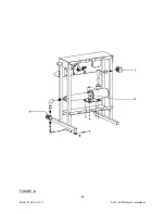
Страница 40: ...40 ENGF 107 REV A 01 11 2011 AXEON Water Technologies FIGURE 6...
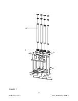
Страница 41: ...41 ENGF 107 REV A 01 11 2011 AXEON Water Technologies FIGURE 7...
Страница 42: ...42 ENGF 107 REV A 01 11 2011 AXEON Water Technologies FIGURE 8...
Страница 47: ...47 ENGF 107 REV A 01 11 2011 AXEON Water Technologies CT 4000 FLOW DIAGRAM...
Страница 48: ...48 ENGF 107 REV A 01 11 2011 AXEON Water Technologies CT 5000 FLOW DIAGRAM...
Страница 49: ...49 ENGF 107 REV A 01 11 2011 AXEON Water Technologies CT 7000 FLOW DIAGRAM...
Страница 50: ...50 ENGF 107 REV A 01 11 2011 AXEON Water Technologies 110 220V 50 60 Hz 1 PHASE ELECTRICAL SCHEMATIC Minitrol...
Страница 51: ...51 ENGF 107 REV A 01 11 2011 AXEON Water Technologies 208 220V 50 60 Hz 3 PHASE ELECTRICAL SCHEMATIC Minitrol...
Страница 54: ...54 ENGF 107 REV A 01 11 2011 AXEON Water Technologies...


