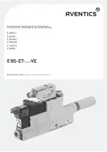
Device description
Function
The ejector is supplied with compressed air via connection (
3
). The compressed air
flowing through generates a vacuum at connection (
2
) and is blown off to the outside
via exhaust openings (
4
). The following functions are possible, depending on the
design:
W
The vacuum can be switched on and off via an electromagnetic valve (
6
).
W
A blow-off pulse can be generated via an electromagnetic valve (
7
) or
pneumatically via an accumulator (
8
).
W
A pressure sensor (
5
) makes it possible to recognize the presence of a vacuum
and to generate a switch pulse.
6
Assembly
Connecting the ejector pneumatics
O
See the EBS-PT operating instructions (R412008280).
Connecting the ejector electrics
Connecting the electromagnetic valve
(only for versions with an electromagnetic valve)
1.
Wire the open cable side with your system.
No polarity must be observed when ap24 V DC (bipolar).
2.
Insert the connector in the socket on the electromagnetic valve until it engages.
Connecting the PE6 pressure sensor
Notes on installation:
W
Install lines that are as short as possible to avoid malfunctions.
W
Connect the line shield to an interference-free ground potential. The shield is not
connected to the sensor.
7
Commissioning
1.
Make sure before commissioning that all the connections on the ejector are
properly connected and all the plastic tubing is firmly fitted.
2.
Apply the compressed air to the system.
3.
Check whether the necessary vacuum has been attained
(e.g. with a pressure gauge).
If using electromagnetic valves:
O
Test the function of the electromagnetic valves.
If using a pressure sensor:
O
Test the function of the pressure sensor.
1
M4 mounting bores
5
Pressure sensor with 2x LED
2
Vacuum connection
6
“Suction” electromagnetic valve
3
Compressed air connection
7
“Blow-off” electromagnetic valve
4
Exhaust connection/silencer
8
Accumulator for blow-off pulse
CAUTION
System is operating under voltage.
Working on the system when under voltage could lead to injuries from an electric
shock and damage to the components!
O
Make sure that all relevant system parts are not under voltage before working
on the system.
Use connector type 10/15, MNR 1834484253 to connect the electromagnetic
valve. (Not included in the delivery contents. Order separately.)
M8x1 plug
Pin
Signal
Cable
1)
1) Max. cable length: 30 m
1
+UB: 24 V supply
brown
2
Out 2: switch output 2, PNP (green LED)
white
3
GND: reference potential
blue
4
Out 1: switch output 1, PNP (yellow LED)
black
1
2
2
1
4
3
8
Operation
O
See the EBS-PT operating instructions (R412008280).
9
Maintenance
The ejector is maintenance-free.
10 Accessories
11 Cleaning and servicing
How to clean the ejector:
1.
Make sure that all relevant system parts are not under voltage or pressure.
2.
Clean the ejector using a slightly damp cloth. Only use water to do this and, if
necessary, a mild detergent.
12 Disassembly and malfunctions
O
See EBS-PT operating instructions (R412008280), chapter 11 “Disassembly” and
chapter 13 “If malfunctions occur”.
13 Disposal
Dispose of the ejector in accordance with the applicable national regulations.
14 Technical data
CAUTION
Heating of the pressure sensor during operation
At high ambient temperatures and low load impedance, the pressure sensor may
heat up to over 60 °C during operation, resulting in a danger of burns.
O
Do not touch the pressure sensor during operation or shortly thereafter.
Please contact the service department at AVENTICS if you have any technical
problems.
Accessory part
Description/art. number
Connecting cable with bushing for solenoid
valves (3 m)
1834484253
CN 1 connection cable for pressure sensor,
M8 push-in fitting 4-pin
1834484144…147
Vacuum filter, cup version VFC, required
with heavy contamination on the suction
side or with fine dust < 50 μm
Filter size G1/8, G1/4, G1/2, G3/4
0821305181…187
NOTICE
Solvents and aggressive cleaning agents
Solvents and aggressive cleaning agents could damage the ejector.
O
Only use water for cleaning and, if necessary, a mild detergent.
Electromagnetic valve
Operating voltage
+24 V DC (-5/+10 %)
Protective extra-low voltage
(PELV acc. to IEC 364-4-41)
Power
1.3 W
ED
100 %
On/off switching time
8/10 ms
Manual override
Depression
Protective circuit
Z-diode (in valve)
Switching state
Via LED
Protection class
IP 40 (with plug)
AVENTICS
| EBS-ET-...-VE | R412013037–BDL–001–AB | English
4


