Issue 2 January 2008
31
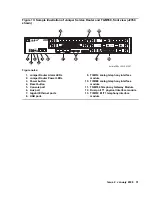
Figure 13: Sample illustration of Juniper Service Router and TGM550, front view (J2350
shown)
Figure notes:
1. Juniper Router Alarm LEDs
2. Juniper Router Power LEDs
3. Power button
4. Reset button
5. Console port
6. Aux port
7. Gigabit Ethernet ports
8. USB ports
9. TIM514 analog telephony interface
module
10. TIM508 analog telephony interface
module
11. TGM550 Telephony Gateway Module
12. Dual port T1 physical interface module
13. TIM510 E1/T1 telephony interface
module
hwma235c LAO 041907
Gateway
ALM
ACT
TGM550
Console
ASB
ETR
RST
Line
Trunk
1
2
3
4
Analog
ALM
ACT
TIM514
Line
5
6
7
8
Line
1
2
3
4
CONSOLE
AUX
USB0
1
2
3
4
5
J2350
PO
W
ER
POWER
RESET
CONFIG
ST
ATUS
ALAR
M
HA
10/100/1000
0/0
0/1
0/2
0/3
LINK TX/RX
LINK TX/RX
LINK TX/RX
TX/RX
LINK
Juniper
NETWORKS
CONFIG
SLOT NUMBER
USB1
ALM
ACT
E1/T1
ALM
ACT
TIM510
TST
SIG
SO
EI
SM
EM
SI
EO
R
1xGE SFP
STATUS
PORT 0
STATUS
PORT 1
7
1
2
3
4
5
6
8
9
10
11
12
13
Содержание IG550
Страница 1: ...Installing and Configuring the Avaya IG550 Integrated Gateway 03 601554 Issue 2 January 2008 ...
Страница 10: ...What procedure you should use 10 Installing and Configuring the IG550 Integrated Gateway ...
Страница 27: ...Issue 2 January 2008 27 Figure 9 DC power connections to the 6350 chassis h LAO 100306 3magnd2 ...
Страница 67: ...Issue 2 January 2008 67 4 From the Summary list click Interfaces The Interfaces screen appears ...
Страница 116: ...Installing an IG550 Integrated Gateway with the CLI 116 Installing and Configuring the IG550 Integrated Gateway ...
Страница 176: ...Recovering passwords 176 Installing and Configuring the IG550 Integrated Gateway ...
Страница 196: ...196 Installing and Configuring the IG550 Integrated Gateway Index ...

