background image

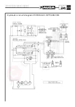
Hydraulic circuit diagram HYDRAULIC APPLIANCES

C 400 H / C 400 HI / C 400 H x4 / C 400 HI x4
C 500 H / C 500 HI / C 500 H x4 / C 500 HI x4

109

Содержание C 400 H

Страница 1: ...C 400 H C 400 HI C 400 H x4 C 400 HI x4 C 500 H C 500 HI C 500 H x4 C 500 HI x4 OPERATOR S MANUAL ENGLISH ORIGINAL MANUAL ...

Страница 2: ......

Страница 3: ...AUSA Forklift C 400 H C 400 HI C 400 H x4 C 400 HI x4 C 500 H C 500 HI C 500 H x4 C 500 HI x4 Above chassis number 30365171 Original Manual ...

Страница 4: ......

Страница 5: ...er This forklift is designed and intended for off highway use If it is temporarily operated on any public street or highway the state and local laws governing speed size weight brakes and lighting must be complied with For further information you may write FAX or E mail to AUSA Center S L U P O B 194 08243 MANRESA Barcelona SPAIN Tel 34 93 874 75 52 93 874 73 11 Fax 34 93 873 61 39 93 874 12 11 93...

Страница 6: ...ipments 59 Operating the forklift 67 Special procedures 71 Recommended fluids and lubricants 73 Maintenance Chart 75 Periodic Maintenance Operations 77 Transporting the forklift 99 Electrical circuit diagram 102 Hydraulic circuit diagram 108 Transmission troubleshooting 112 EC Certificate of conformity 113 C 400 H C 400 HI C 400 H x4 C 400 HI x4 C 500 H C 500 HI C 500 H x4 C 500 HI x4 4 Contents ...

Страница 7: ...pair work the occupational health and safety regulations together with those relative to accident prevention should be observed When driving with the forklift on public highways special care should be taken to ensure compliance with the current legislation for this type of vehicle Highway Code AUSA does not assume responsibility for any damage resulting from modifications made to the forklift with...

Страница 8: ...is engraved on the right hand strut of the chassis Engine serial number figs 3 4 This is engraved on the right hand side of the engine below the exhaust manifold and is also given on a label on the rocker arm cover Identification plates of the principal components The identification plates corresponding to all those components not directly constructed by AUSA for example engines pumps etc are loca...

Страница 9: ...eight H with mast extended ALL MODELS ALL MODELS mm in mm in mm in mm in 3700 12ft 2in 100 3 2 in 2750 9ft 0 2 in 4585 15ft 0 4 in 4500 14ft 9in 100 3 2 in 3150 10ft 3 3in 5385 17ft 6 6in 4250 13ft 11in 1393 4ft 5 7 in 2350 7ft 7in 5262 17ft 2 6in 5400 17ft 8in 1793 5ft 8 8 in 2750 9ft 0 2 in 6462 21ft 20in 6800 22ft 4in 2243 7ft 3 5 in 3200 10ft 4 9in 7812 25ft 6 2in Maximum lifting heigh Free li...

Страница 10: ...on the lower part of the joystick A lamp in the shape of an arrow lights up on the top of it when a movement mode is selected Steering Hydraulic powered Drive is in the rear axle through a double acting hydraulic cylinder Operating pressure C400H HI C500H HI 2175 psi 150 bar C400H HI x4 C500H HI x4 2465 psi 170 bar External turning circle C400H HI C500H HI 11 ft 6 7 in 3560 mm C400H HI x4 C500H HI...

Страница 11: ...r 123 psi 8 5 bar C400HI x4 123 psi 8 5 bar 123 psi 8 5 bar C500HI 123 psi 8 5 bar 123 psi 8 5 bar C500HI x4 123 psi 8 5 bar 123 psi 8 5 bar Operating temperature From 5º F to 104 ºF from 15ºC to 40ºC Vibration and sound levels Sound on the operator s site Warranteed sound power according to 2000 14 CE LwA 102 dB A A weighted sound pressure in the operator s ear measured following norms EN 12053 a...

Страница 12: ...oil level battery charge and coolant temperature Weights Unladen weight with full tanks C400H HI 14770 lbs 6700 kg C400H HI x4 14991 lbs 6800 kg C500H HI 16534 lbs 7500 kg C500H HI x4 16755 lbs 7600 kg Fully laden weight C400H HI 23589 lbs 10700 kg C400H HI x4 23810 lbs 10800 kg C500H HI 27558 lbs 12500 kg C500H HI x4 27779 lbs 12600 kg Load capacity C400H HI C400H HI x4 8818 lbs 4000 kg With load...

Страница 13: ... 5ft 88 in 17ft 71in 21ft 02in TRIPLEX 22ft 30in 10ft 49in 7ft 35in 22ft 14in 25ft 62in OPTIONAL C400 500H HI in MÁSTIL Lift height mm h1 mm h2 mm h3 mm h4 mm DUPLEX 3700 2750 100 3650 4585 DUPLEX 4500 3150 100 4450 5385 TRIPLEX 4250 2350 1393 4200 5262 TRIPLEX 5450 2750 1793 5400 6462 TRIPLEX 6800 3200 2243 6750 7812 OPTIONAL C 400 H C 400 HI C 400 H x4 C 400 HI x4 C 500 H C 500 HI C 500 H x4 C 5...

Страница 14: ...nto the steering column and below the joystick Lighting Operating lights park lights indicators and hazard warning light equipment Overhead guard Constructed in accordance with ISO 3449 ISO 3471 and ASME B56 6 standards WARNING The operator is protected by an overhead guard which complies with the ISO 3449 ISO 3471 and ASME B56 6 standards It provides protection against falling objects and togethe...

Страница 15: ... on grounds not in good condition roughly flat not too steep slopes and small obstacles so that the stability conditions are not optimal Load charts for C 400H C 400H x4 500 mm load centre C 400 H C 400 HI C 400 H x4 C 400 HI x4 C 500 H C 500 HI C 500 H x4 C 500 HI x4 13 Technical specifications ...

Страница 16: ...Load charts for C 400H C 400H x4 600 mm load centre C 400 H C 400 HI C 400 H x4 C 400 HI x4 C 500 H C 500 HI C 500 H x4 C 500 HI x4 14 Technical specifications ...

Страница 17: ...Load charts for C 400H C 400H x4 24 in load centre C 400 H C 400 HI C 400 H x4 C 400 HI x4 C 500 H C 500 HI C 500 H x4 C 500 HI x4 15 Technical specifications ...

Страница 18: ...Load charts for C 500H C 500H x4 600 mm load centre C 400 H C 400 HI C 400 H x4 C 400 HI x4 C 500 H C 500 HI C 500 H x4 C 500 HI x4 16 Technical specifications ...

Страница 19: ...Load charts for C 500H C 500H x4 24 in load centre C 400 H C 400 HI C 400 H x4 C 400 HI x4 C 500 H C 500 HI C 500 H x4 C 500 HI x4 17 Technical specifications ...

Страница 20: ...ing loads on good condition floors that means flat levelled and paved ground so that there are optimal stability conditions Load charts for C 400HI C 400HI x4 500 mm load centre C 400 H C 400 HI C 400 H x4 C 400 HI x4 C 500 H C 500 HI C 500 H x4 C 500 HI x4 18 Technical specifications ...

Страница 21: ...Load charts for C 400HI C 400HI x4 600 mm load centre C 400 H C 400 HI C 400 H x4 C 400 HI x4 C 500 H C 500 HI C 500 H x4 C 500 HI x4 19 Technical specifications ...

Страница 22: ...Load charts for C 400HI C 400HI x4 24 in load centre C 400 H C 400 HI C 400 H x4 C 400 HI x4 C 500 H C 500 HI C 500 H x4 C 500 HI x4 20 Technical specifications ...

Страница 23: ...Load charts for C 500HI C 500HI x4 600 mm load centre C 400 H C 400 HI C 400 H x4 C 400 HI x4 C 500 H C 500 HI C 500 H x4 C 500 HI x4 21 Technical specifications ...

Страница 24: ...Load charts for C 500HI C 500HI x4 24 in load centre C 400 H C 400 HI C 400 H x4 C 400 HI x4 C 500 H C 500 HI C 500 H x4 C 500 HI x4 22 Technical specifications ...

Страница 25: ...ont and rear Radio Load guard Where the forklift comes equipped with accessories mounted at factory please read the relevant Instruction Manual for each accessory carefully before use Each accessory has its own Instruction Manual issued by the manufacturer and this is provided with the forklift Operator s and Safety Manual Where accessories and equipment are fitted to the basic chassis or fork car...

Страница 26: ... 01 DESCRIPTION INDICATIVE STICKER MAST SIDE SHIFT QUANTITY 1 POSITION Stuck on the inside of the right front fender in the top center position Just above sticker ref 10 15003 01 at 0 1969 in STICKER DANGEROUS AREA REFERENCE 45 01352 00 DESCRIPTION INDICATIVE STICKER QUANTITY 2 POSITION On both sides of the mast above the beam with its upper side aligned at 4ft 92 in from the ground below the stic...

Страница 27: ...KER QUANTITY 2 POSITION On both sides of the machine at a distance of 0 984 in and a height of 1 969 in from the lower rear corner of each tank aligned with the bottom of the tank STICKER TURBOCHARGER REFERENCE 20 12012 00 DESCRIPTION INDICATIVE TURBOCHARGER STICKER QUANTITY 2 POSITION On both sides of the machine above the AUSA sticker ref 13 12136 00 at a distance of 0 1969 in height and aligned...

Страница 28: ... DESCRIPTION INDICATIVE STICKER 8 5 BAR 123 PSI QUANTITY 2 POSITION On both sides of the machine on top of the vertical face in the upper rear position of each tank aligned with the bottom of the tank STICKER REAR AXLE WHEELS INFLATED PRESSURE C400Hx4 C500Hx4 REFERENCE 32 12102 00 DESCRIPTION INDICATIVE STICKER 6 BAR 87 PSI QUANTITY 2 POSITION On both sides of the machine on top of the vertical fa...

Страница 29: ... 500HI C400 500HI x4 REFERENCE 01 12108 00 DESCRIPTION INDICATIVE STICKER 8 5 BAR 123 PSI QUANTITY 2 POSITION On both sides of the machine on top of the vertical face in the upper rear position of each tank aligned with the bottom of the tank STICKER FUEL TYPE INDICATION REFERENCE 43 01356 00 DESCRIPTION INDICATIVE STICKER 90x45 FUEL QUANTITY 1 POSITION On the right tank of the machine next to the...

Страница 30: ...INDICATIVE STICKER 70x32 HYDRAULIC OIL QUANTITY 1 POSITION On the left hand side tank below the filler cap aligned with the inner edge of the tank and centered with the cap STICKER ENGINE OIL TYPE REFERENCE 43 01170 02 DESCRIPTION INDICATIVE STICKER 90x45 QUANTITY 1 POSITION On top of part ref 57 08011 00 fixed part of the cab lock on the right hand side in forward direction of machine easily legi...

Страница 31: ...VE STICKER 68x267 MODEL C500H QUANTITY 2 POSITION On both sides of the machine at a distance of 1 969 in and a height of 5 906 in from the lower rear corner of each tank aligned with the bottom of the tank STICKER MACHINE MODEL INDICATION C400 HI C400HI x4 REFERENCE 30 12001 01 DESCRIPTION INDICATIVE STICKER 68x267 MODEL C400HI QUANTITY 2 POSITION On both sides of the machine at a distance of 1 96...

Страница 32: ... REFERENCE 01 00779 26 DESCRIPTION PLATE CHARACTERISTICS 100x130 QUANTITY 1 POSITION Riveted on top of the engine bulkhead on its rear upper left hand side in forward direction of machine in the holes prepared Etched according to assembly instruction STICKER AUSA ANAGRAM REFERENCE 46 08099 00 DESCRIPTION AUSA ANAGRAM QUANTITY 1 POSITION Embedded in the cab front panel on its outer side in the uppe...

Страница 33: ...7 00 DESCRIPTION INDICATIVE STICKER D40 QUANTITY 1 POSITION Top left hand corner of the instrument panel under sticker 02 00774 00 Do not use aligned with this on its right side and centered with sticker ref 12 12010 00 STICKER POINT HOISTED MACHINE REFERENCE 09 15720 00 DESCRIPTION INDICATIVE STICKER 35x35 QUANTITY 4 POSITION Above each of the four eyebolts at the bottom of the frame for lifting ...

Страница 34: ...2 POSITION On both sides of the machine next to the AUSA sticker ref 13 12136 00 and aligned on the right side STICKER MAST LOWERING MARKER MACHINES WITH SEMI CLOSED AND FULL CAB REFERENCE 57 12010 00 DESCRIPTION INDICATIVE STICKER LOWERING MAST QUANTITY 1 POSITION On the rear window of the cab centered with the cab opening lever aligned with the bottom of the window 0 3937 in away from the rubber...

Страница 35: ...heated enclosed cab position at the bottom left hand side of the window 0 3937 in away from the edge bottom left side n away from the edge bottom left side STICKER AUSA STICKER REFERENCE 13 12136 00 DESCRIPTION AUSA STICKER QUANTITY 2 POSITION On both sides of the mast above the beam with its lower side aligned at 4ft 95 in from the ground above the sticker ref 45 01352 00 Dangerous area and 0 393...

Страница 36: ...DESCRIPTION INDICATIVE STICKER 50x120 ENGLISH QUANTITY 1 POSITION Top left hand corner of the dashboard aligned on its left side with sticker nº 12 12010 00 Safety warning STICKER BRAKE FLUID INDICATION REFERENCE 43 70780 01 DESCRIPTION INDICATIVE STICKER 60x100 BRAKE QUANTITY 1 POSITION In the engine compartment on the left side of the brake fluid bottle aligned with this bottle Trim the foam rub...

Страница 37: ... STICKER LOAD CHART PLATE REFERENCE 43 01350 28 30 12004 00 DESCRIPTION INDICATIVE PLATE 91x156 LOAD CHARTS QUANTITY 1 POSITION Riveting in 4 holes provided in the central outer part the left hand front fender Etched according to assembly instruction Add another unit at the top in the event of installing a mast higher than 12ft 14 in C 400 H C 400 HI C 400 H x4 C 400 HI x4 C 500 H C 500 HI C 500 H...

Страница 38: ...REFERENCE 58 01353 01 DESCRIPTION INDICATIVE STICKER 105X100 QUANTITY 2 POSITION On both sides of the machine at the lower exterior part of the front fenders aligned on its upper side with sticker 45 19101 00 EC mark STICKER AUSA C400 500H Hx4 REFERENCE 13 12136 00 DESCRIPTION AUSA STICKER QUANTITY 2 POSITION On both sides of the machine at a distance of 0 984 in and a height of 1 969 in from the ...

Страница 39: ...NDICATIVE STICKER 6 BAR 87 PSI QUANTITY 2 POSITION On both sides of the machine above the fenders of the front wheels at the front outer end of the fenders aligned with the outer edge STICKER REAR AXLE WHEELS INFLATED PRESSURE C400 500H REFERENCE 01 12108 00 DESCRIPTION INDICATIVE STICKER 8 5 BAR 123 PSI QUANTITY 2 POSITION On both sides of the machine on top of the vertical face in the upper rear...

Страница 40: ...SCRIPTION INDICATIVE STICKER 8 5 BAR 123 PSI QUANTITY 2 POSITION On both sides of the machine above the fenders of the front wheels at the front outer end of the fenders aligned with the outer edge STICKER REAR AXLE WHEELS INFLATED PRESSURE C400HI 500HI C400 500HI x4 REFERENCE 01 12108 00 DESCRIPTION INDICATIVE STICKER 8 5 BAR 123 PSI QUANTITY 2 POSITION On both sides of the machine on top of the ...

Страница 41: ...ON On both sides of the machine at the bottom inner side of the front fenders aligned on its upper side with mark id 58 01353 01 To hoist machine STICKER MACHINE MODEL INDICATION C400H C400H x4 REFERENCE 30 12001 00 DESCRIPTION INDICATIVE 68x267 MODEL C400H QUANTITY 2 POSITION On both sides of the machine at a distance of 0 984 in and a height of 5 906 in from the lower rear corner of each tank al...

Страница 42: ...STICKER 68x267 MODEL C400HI QUANTITY 2 POSITION On both sides of the machine at a distance of 1 969 in and a height of 5 906 in from the lower rear corner of each tank aligned with the bottom of the tank STICKER MACHINE MODEL INDICATION C500HI C500HI x4 REFERENCE 30 12002 01 DESCRIPTION INDICATIVE STICKER 68x267 MODEL C500HI QUANTITY 2 POSITION On both sides of the machine at a distance of 1 969 i...

Страница 43: ...ER QUANTITY 1 POSITION Top left hand corner of the dashboard under sticker ref 02 00774 00 Do not use and aligned with this on its left side STICKER OPERATOR ACOUSTIC PROTECTION REFERENCE 01 00757 00 DESCRIPTION INDICATIVE STICKER D40 QUANTITY 1 POSITION Top left hand corner of the instrument panel under sticker 02 00774 00 Do not use aligned with this on its right side and centered with sticker r...

Страница 44: ...4 00 DESCRIPTION ADHESIVE NOISE 104 DB QUANTITY 1 POSITION On the inside of the right front wheel arch aligned with the cab floor STICKER FUILL GRIP C400 500H x4 C400 500HI x4 REFERENCE 43 00397 00 DESCRIPTION INDICATIVE STICKER 110x110 QUANTITY 2 POSITION On both sides of the machine next to the AUSA sticker ref 13 12136 00 and aligned on the right side C 400 H C 400 HI C 400 H x4 C 400 HI x4 C 5...

Страница 45: ...R NON MOVEMENTS WITH LOAD OFFCENTERED MASTS OF MORE THAN 12ft 2 in SUBSTITUTE REF 43 02187 02 REFERENCE 43 02187 02 DESCRIPTION INDICATIVE STICKER 70x210 ENGLISH QUANTITY 1 Cab heated POSITION On top of the tablier next to the adhesive ref 10 01414 01 Indication structure aligned with it by their side In heated enclosed cab position at the bottom left hand side of the window 0 3937 in away from th...

Страница 46: ...EFERENCE 43 00396 02 DESCRIPTION INDICATIVE STICKER 60x95 QUANTITY 1 POSITION At the top of the transfer case with the text facing the oil filler cap Centered with the casting lugs STICKER BRAKE FLUID INDICATION REFERENCE 43 70780 01 DESCRIPTION INDICATIVE STICKER 60x100 BRAKE QUANTITY 1 POSITION In the engine compartment on the left side of the brake fluid bottle aligned with this bottle Trim the...

Страница 47: ...n 4 holes provided in the central outer part the left hand front fender Etched according to assembly instruction Add another unit at the top in the event of installing a mast higher than 12ft 14 in STICKER REFLECTIVE TRIANGLE WITH PLATE MACHINE WITH OPEN CAB USA REFERENCE 10 15120 00 DESCRIPTION INDICATIVE STICKER 350x400 QUANTITY 1 POSITION Fixed at the bottom edge of the cab rear opening centere...

Страница 48: ...03 01 REFERENCE 10 15006 01 DESCRIPTION INDICATIVE STICKER LEVER LOW CONTROL QUANTITY 1 POSITION Stuck on the inside of the right hand front fender top center position STICKER CHARACTERISTICS PLATE SUBSTITUTE REF 01 00779 26 REFERENCE 01 00779 23 DESCRIPTION CHARACTERISTICS PLATE 100x130 SPECIAL QUANTITY 1 POSITION Riveted on the engine bulkhead on its rear side in the holes provided Etched accord...

Страница 49: ...ESCRIPTION INDICATIVE STICKER 90x45 QUANTITY 1 POSITION On top of part ref 57 08011 00 fixed part of the cab lock on the right hand side in forward direction of machine easily legible with the cab raised STICKER HYDRAULIC OIL TYPE USA SUBSTITUTE REF 43 01352 20 REFERENCE 60 01352 01 DESCRIPTION INDICATIVE STICKER 40x87 HYDRAULIC OIL QUANTITY 1 POSITION On the left hand side tank below the filler c...

Страница 50: ...way from it STICKER NOT TO TOUCH INDICATION REFERENCE 02 00766 00 DESCRIPTION INDICATIVE STICKER 40x80 USA QUANTITY 1 POSITION On the top of the radiator fan guard STICKER PROTECTION STRUCTURE INDICATION REFERENCE 10 01414 01 DESCRIPTION INDICATIVE STICKER 60x125 USA QUANTITY 1 POSITION In the upper left hand corner of the dashboard aligned at the left with the adhesive ref 10 01414 01 Warning Sec...

Страница 51: ... 01171 00 DESCRIPTION INDICATIVE STICKER 42x77 QUANTITY 1 POSITION In the upper right hand corner of the dashboard aligned at the top with the bend in the dashboard C 400 H C 400 HI C 400 H x4 C 400 HI x4 C 500 H C 500 HI C 500 H x4 C 500 HI x4 49 ...

Страница 52: ...d maintenance of equipment on a worksite Because it is an employer s responsibility to apply these laws an OSHA representative may periodically inspect a worksite to see that these laws are being followed There may also be local or state provincial laws that apply to this equipment and its use along with specific worksite or employer rules It is important that you know and apply all applicable law...

Страница 53: ...ufficient ventilation to prevent excessive build up of exhaust fumes Under this conditions always stop this engine when not in use Before starting the forklift be certain to check or test the following items Check for any leaks in the fuel hydraulic or cooling system Clean any oil or fuel leaks that may exist on the forklift controls or operating area Check tire conditions and pressures Re tight w...

Страница 54: ...t on this Operator s and Safety Manual Work circuit The movement of loads within an installation or enclosure must be carried out following certain instructions concerning the circulation of forklifts and pedestrians If you are not aware of these regulations please check with your supervisor Study the movements of the forklift to avoid making manoeuvres which are unnecessary or involve risk to the...

Страница 55: ...diments of dynamic equilibrium While the forklift is moving and as it gains speed the equilibrium conditions of the load forklift unit are modified as the centre of gravity shifts This is accentuated on lifting loads turning braking etc In these conditions it is necessary to take the utmost care to ensure that the centre of gravity of the load is maintained within the specifications showed on the ...

Страница 56: ...f the forks and the forklift machine itself Make certain that long or wide loads are fastened together so as to be stable and secure The load and counterweight The load should be lifted and lowered with the mast in vertical position or slightly tilted backwards The raised load should only be tilted forwards when it is about to be unloaded Tilting the load forwards or backwards swinging is very use...

Страница 57: ...he slope Do not travel across an incline Never position the forklift sideways on a slope Forks should only be raised on level stable ground You must be the judge whether ground conditions will permit the safe operation of the forklift Operation on an incline can be very dangerous Rain snow loose gravel or soft ground can be factors which may prevent the use of the forklift Keep the forks and the l...

Страница 58: ...lift should be free of obstacles and pedestrians however if their presence is necessary the pedestrians should move in areas which have been duly marked as such and they should be easily distinguished for example by wearing reflective jackets If the area is closed it should be well ventilated and the forklift must be equipped with lighting and exhaust gas purifier systems The forklift operator sho...

Страница 59: ...ructure must not be repaired but replaced for a new one When leaving parking the forklift fig 1 2 3 A poorly parked forklift truck is a risk Park the forklift in the areas provided for this purpose without obstructing the passage of others exits or entrances to stairs and emergency equipment Place the forks or attachment in the fully lowered position Set all the controls in the 0 neutral position ...

Страница 60: ...C 400 H C 400 HI C 400 H x4 C 400 HI x4 C 500 H C 500 HI C 500 H x4 C 500 HI x4 58 Special Safety Messages ...

Страница 61: ... viewed from the operator s seat looking forward Description of parts 1 Lifting Mast 2 Lighting equipment 3 Joystick 4 Operator overhead guard 5 Rotating beacon 6 Diesel tank placed symmetrically to the hydraulic oil tank 7 Hydraulic oil tank 8 Operator s seat with seatbelt 9 Mast forks C 400 H C 400 HI C 400 H x4 C 400 HI x4 C 500 H C 500 HI C 500 H x4 C 500 HI x4 59 Controls Instruments Equipmen...

Страница 62: ...ights up When the direction arrows are not lit the direction of travel control is at the stop position neutral By pressing the front of the switch the machine travels forwards and by pressing the rear of the switch the machine travels backwards Safety When the parking brake is not on and or the operator is not sitting in the driver s seat the direction arrows are also switched off and the directio...

Страница 63: ...e mast and the forks lower Tilting the forks If the joystick is pulled to the left the mast forks tilt backwards forks lift and if pushed to the right they tilt forward forks lower Side shift By holding down button 5 on the joystick and pulling the joystick to the left the forks move to the left By holding down button 5 and pushing the joystick to the right the forks move to the right Always centr...

Страница 64: ...nstrument 2 Lights switch 3 Heating switch 4 Horn switch 5 Parking brake 6 Windscreen wiper switch 7 Rotating beacon switch 8 Indicators switch 9 Working light switch 10 Hazard lights switch C 400 H C 400 HI C 400 H x4 C 400 HI x4 C 500 H C 500 HI C 500 H x4 C 500 HI x4 62 Controls Instruments Equipments 1 10 9 8 7 6 5 2 3 4 fig 1 ...

Страница 65: ...s on the low beam and the second switches on the high beam 3 Heating switch This has two positions to give two fan speeds 4 Horn switch To activate the horn press the switch 5 Parking brake To activate the forklift parking brake press the switch 6 Windscreen wiper switch To switch on the windscreen wiper press the switch To activate the windscreen wiper washer pump press the same switch again 7 Ro...

Страница 66: ...diately E Preheating warning lamp When this lamp glows it indicates that the engine pre heat plugs are in operation and heating the combustion chamber to the temperature required in order to start the engine F Hydraulic oil level warning lamp This lights up and emits an audible warning when the hydraulic oil level is at the minimum level Oil should be added to top up the level to the correct level...

Страница 67: ...unsuitable additives The correct fuel for the forklift is diesel For further details regarding fuel type and required specifications see the section FLUIDS AND LUBRICANTS Do not allow the fuel to come into contact with the skin and avoid inhaling the fumes which are toxic High concentrations of fuel vapour may cause sickness loss of consciousness or even loss of life in the event of prolonged expo...

Страница 68: ...mfortably Apply the parking brake switch off the engine and lights including the rotating beacon Note If the fuel pump is equipped with a vehicle earth connection connect this to an unisolated metal component of the forklift Clean the fuel cap and surrounding area with a cloth if they have been dirtied Do not allow dust water or any other substance to enter the tank Open the fuel cap using the key...

Страница 69: ...ob a and sliding seat to the desired position then releasing the knob to lock the seat into position The seat may be adjusted for drivers weight by lifting or lowering lever b downwards to the relevant position as indicated by the scale in de middle of the seat It is also possible to adjust the seat backrest angle The seat backrest tilts forward or backwards by lifting knob c The position of the s...

Страница 70: ...e accelerator pedal 1 4 of the way and turn the key to position c to start the engine Do not hold the key in this position for more than 15 seconds If the engine does not start repeat the above steps and wait 30 seconds between each attempt Before re starting the engine the key should first be switched to position a Checks With the engine running and the forklift at idle carry out the following ch...

Страница 71: ...5 kg and the C500H and C500H x 4 has a rated capacity of 11023lbs 5000 kg Industrial use With load center at 20in 500 mm from vertical face of the forks the C400HI and C400HI x4 has a rated capacity of 8818lbs 4000 kg With a load center at 24in 600 mm from the vertical face of the forks the C400HI and C400HI x 4 has a rated capacity of 8146lbs 3695 kg and the C500HI and C500HI x 4 has a rated capa...

Страница 72: ...of tipping over Load charts fig 1 2 3 The charts you can see in the section TECHNICAL SPECIFICATIONS on this Operator s and Safety Manual shows how much your forklift can lift as the load centre increases out to 4in Note how the lift capacity decreases as the load centre increases This chart is reproduced as a machine decal and is located on both the right and the left side of the mast and at the ...

Страница 73: ...ible After use care When the forklift is used in salt water areas beach areas etc rinse the machine with fresh water to protect the forklift and its components from rust We recommend lubricating the metal components This should be carried out at the end of every day after using the forklift When the forklift has been working in muddy areas it should be washed with fresh water to protect the forkli...

Страница 74: ...er contact to an authorized AUSA dealer as soon as possible Immersion of the forklift If the forklift becomes submerged under water it will be necessary to take it to an authorized AUSA dealer as soon as possible WARNING DO NOT START THE ENGINE Immersion of the forklift may cause serious damage to the engine if the start up procedures are not followed correctly Arrange for an authorized AUSA deale...

Страница 75: ...FRONT AXLE PLANETARY REDUCTION Transmission oil SAE 80W90 in accordance with API GL4 MIL L 2105 See FRONT AXLE AND FullGrip SYSTEM in this section 461 00099 09 0 22 0 85 REAR AXLE DIFF 4x4 Transmission oil SAE 80W90 in accordance with API GL4 MIL L 2105 461 00004 01 0 95 3 6 4x4 REAR AXLE PLANE TARY REDUC TION Transmission oil SAE 90 in accordance with API GL4 MIL L 2105B 461 00004 01 0 1 0 35 4x2...

Страница 76: ...ures between 50F to 120ºF 10ºC to 40ºC VG 68 for environment temperatures above 120ºF 40ºC Front axle and FullGrip System Use oil for COMPEN AUSA which meets with the following characteristics Friction coefficient modifying additives Extreme Pressure and anti wear capacity Good antirust and anticorrosion characteristics Excelent thermal stability Avoids vibrations and noise Brake and inching fluid...

Страница 77: ...timer 2 I DEALER COOLING SYSTEM Radiator hoses and clamps bands I R USER Water jacket radiator interior C DEALER Cooling system pressure test I USER Radiator exterior 4 C USER Coolant I R USER ELECTRICAL SYSTEM Battery electrolyte I I USER Battery connections I USER Dash panel indicators Warning lights 3 I USER Battery I R USER Electric harness and loose connections I USER HYDRAULIC CIRCUIT Oil an...

Страница 78: ... fixation screws torque I DEALER Cardan joints fixation screws torque I DEALER Flange fixation nut torque I DEALER Condition of tires and pressures I USER BRAKES Brake fluid 3 R I R USER Brake pedal and master cylinder clearance 3 I I USER Service brake adjustment I DEALER Negative brake adjustment I I DEALER BODY FRAME FOPS ROPS frame I USER Seat belt 3 I USER Access steps and handles 3 I C USER ...

Страница 79: ... recycling centres In the event of leaks of substances which may be harmful to persons or to the environment immediately take the necessary measures to reduce their impact for example in the case of oil leaks plug the leak use a recipient to collect the oil sprinkle absorbent material or collect up and remove the contaminated soil if necessary Access to engine and transmission for maintenance The ...

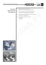
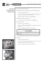
Страница 80: ...g 4 c and nut fig 4 d and remove the rear wheel cover There is a wheel cover on each side of the machine Daily checks Before starting to work with the forklift clean any oil or fuel spills clean and remove grease from hands and the soles of shoes and do not forget to make the following checks Condition of the lifting chains Tyre pressure and condition of the tread Brakes Leaks in the hydraulic coo...

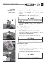
Страница 81: ...ion Clean and check lighting and signaling system are operating correctly Check electrical battery connections and level of electrolyte Adjust the seat to your build Daily checks of the seatbelt for defects such as Cuts loose threads poor stitching Wear or damage to anchor points Poor operation of the seatbelt buckle or retracting roller Correct any problems before using the forklift When necessar...

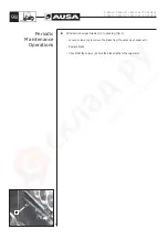
Страница 82: ...clean cloth Set the dipstick into its casing Remove again and check the oil level This should be at the upper level fig 1 a Full b Add oil c Operating range Add oil until the level reaches the upper level Oil level Correct Remove the dipstick and place a funnel in the opening of the oil filler neck located above the rocker arm cover CAUTION Do not exceed the maximum level mark Starting the engine ...

Страница 83: ...ter cartridge by turning it to the left Clean the base of the filter and oil the seal of the new filter element Screw on the new filter element and tighten it by hand without using mechanical means Dispose of the used oil filter cartridge in an authorized centre for this purpose Engine oil Filling up Remove the dipstick and place a funnel in the opening of the oil filler neck located above the roc...

Страница 84: ...the expansion tank with coolant Check the engine hoses and radiator for possible coolant leaks Coolant circuit Draining The coolant should be changed according to FLUIDS AND LUBRICANTS CHART references and capacities or when the circuit is drained for repair purposes To do so proceed as follows Place a container below the radiator Disconnect the lower radiator hose in order to drain the radiator h...

Страница 85: ... replaced as soon as possible CAUTION Do not start the engine when there is water inside the air filter casing When there are fluids or dirt inside the casing the filter cartridges should be inspected drained or replaced Undo the left and right hand staples of the filter cover and remove the cover To clean the filter element blow high pressure air maximum 72 5 PSI through the element from the insi...

Страница 86: ...Unscrew by turning to the left the cartridge c of the fuel filter fig 2 located on the left hand side of the engine and remove it from the support Clean the base and oil the seal of the new filter Screw on the new filter element and tighten by hand without using mechanical means Dispose of remains of fuel in authorized centres WARNING Take care to correctly tighten the filter element otherwise the...

Страница 87: ...ate incorrectly Tilting the mast while the engine is stopped emergency movement It is possible to tilt the mast of the forklift emergency movement forwards with the ignition off To do so proceed as follows Locate the emergency movement connector under the dash panel next to the steering column fig 2 Remove the protective cover from the connector by lifting the locking tab and moving it forwards Wi...

Страница 88: ...prestressing them and make sure that a clearance b is left between cylinder 4 an d lever 19 Also check that when pressure is released piston 13 projects out by 0 16 0 19 in 4 5 mm fig 2 Brake and inching fluid Checking the level With the forklift parked on a level surface the level of the brake fluid in the tank should lie between the marks MIN and MAX fig 3 If necessary top up the brake fluid in ...

Страница 89: ...specified oil through the filler cap a fig 1 bleeder located on the upper part See the FLUIDS AND LUBRICANTS CHART references and capacities in this Operator s and Safety Manual for oil specs and capacity Dispose of used oil in authorized centres fig 1 a fig 3 fig 2 b c C 400 H C 400 HI C 400 H x4 C 400 HI x4 C 500 H C 500 HI C 500 H x4 C 500 HI x4 87 Periodic Maintenance Operations ...

Страница 90: ...ials use the cap fig 4 c Dispose of used oil in authorized centres Oil level in the rear axles differential 4x4 models This should be checked while the forklift is on flat ground Fig 5 Filling checking hole a and b draining hole c Checking To check the oil level unscrew the cap a b fig 5 The oil should be at the level of the casing Draining To drain the oil unscrew the plug c located on the lower ...

Страница 91: ...y covering it with a cloth or similar To drain the oil turn the wheel hub until plug fig 2 b is located on the lower part of the wheel hub Dispose of used oil in authorized centres Planetary reduction Topping up Turn the wheel until the mark Oil Stand Level on the reducer is horizontal Fill with the specified oil through the opening of the plug b See the FLUIDS AND LUBRICANTS CHART references and ...

Страница 92: ...the specified oil through the plug hole Fig 1 a See FLUIDS AND LUBRICANTS CHART references and capacities in this Operator s and Safety Manual for oil specs and capacity Clean the hydraulic oil strainer There is a oil strainer filter located on the interior of the tank in the hydraulic circuit This is a metal filter which should be cleaned every time the hydraulic oil is drained To do so remove th...

Страница 93: ...the locknut To increase the hydraulic pressure turn the screw clockwise using an allen key To reduce the pressure turn the interior screw in the opposite direction Hydrostatic transmission filter Replacing The hydrostatic circuit has a cartridge filter fig 3 which should be replaced regularly See MAINTENANCE CHART Undo the cartridge filter by turning it to the left Clean the base of the filter and...

Страница 94: ...king tyre pressures and inflation should be carried out with a manometer in good condition fitted with a nozzle with safety clip The safety clip is essential for preventing the manometer nozzle from coming off the tyre valve during inflation which could cause serious injury to the operator Use gloves to protect hands Wheel mounted on the machine This should be checked while the forklift is on flat...

Страница 95: ...ion and length of mast chains The tension and length of the mast chains should be checked regularly They stretch gradually due to the strain applied to them The mast chains should be replaced when their nominal length has increased by 3 Length can be checked by counting the links in 39 4in 1m of 1 25 4mm chain Nominally there should be the length of 39 links The change should be made when there is...

Страница 96: ...ation of the axle fig 3 4 nipples two on each wheel reduction joint fig 4 Cardan shafts All models 2 nipples one on each cross fig 5 1 nipple on the grooving fig 5 Brake cylinder pins All models 2 nipples one on each side fig 6 and fig 7 fig 1 fig 2 fig 3 fig 4 fig 5 fig 6 fig 7 Periodic Maintenance Operations C 400 H C 400 HI C 400 H x4 C 400 HI x4 C 500 H C 500 HI C 500 H x4 C 500 HI x4 94 ...

Страница 97: ...r fig 1 2 nipples one on each support of the articulation Tilting cylinder articulation with the chassis fig 1 2 nipples one on each support Articulations of the controls fig 2 Inching pedal Brake pedal fig 1 fig 2 Periodic Maintenance Operations C 400 H C 400 HI C 400 H x4 C 400 HI x4 C 500 H C 500 HI C 500 H x4 C 500 HI x4 95 ...

Страница 98: ...clip fastening the bulb by pressing it inwards and to the right at the same time Replace the bulb with a new bulb of the same type and power CAUTION Do not touch the surface of the glass of the bulb If it is dirty wipe gently using a clean dry cloth Secure the clip again by pressing it inwards and to the left at the same time Indicator bulb Remove the connector from the bulb Remove the bulb by pre...

Страница 99: ... it outwards The burnt fuse can be recognised as the metal strip which is visible in the centre of each fuse will have melted viewing window Remove the burnt fuse and replace with a new fuse of the same type CAUTION Do not use fuses of a higher value this could cause major damage Battery fuses checking fig 4 Switch off the ignition Remove the protective cover from the fuses c The burnt fuse can be...

Страница 100: ...s a to remove the blade from the windscreen wiper arm Replace blade Check that the screws a hold the blade tightly to the wiper arm fig 1 a Periodic Maintenance Operations C 400 H C 400 HI C 400 H x4 C 400 HI x4 C 500 H C 500 HI C 500 H x4 C 500 HI x4 98 ...

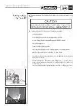
Страница 101: ...avel control switch to neutral Apply the parking brake Lower the forks as far as possible Place a bulk under the ends of each fork and tilt the mast slightly forwards Stop the engine and remove the key from the ignition switch Once the machine has been loaded onto the lorry trailer place chocks behind each of the four wheels Tie the forklift tightly to the platform using suitable securing systems ...

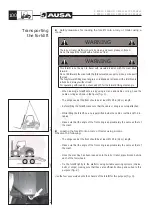
Страница 102: ... Before lifting the forklift make sure that the cable or sling is securely attached While lifting the forklift no one is permitted inside the cabin or within a 16ft 5 in radius Make sure that the angle of the front sling is approximately the same as that of the mast Loading the forklift onto a lorry or trailer using a crane Observe the following The slings used at the front should be at least 8ft ...

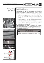
Страница 103: ...ts of the maximum pressure valve of the hydrostatic pump and re tighten the counter nuts The forklift should be towed using a solid towing bar to prevent any lateral oscillation The bar should be fixed to the rear bolt of the counterweight fig 2 Release the parking brake fig 3 4 In the event that the parking brake is blocked due for example to a loss of brake fluid or because the engine does not s...

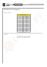
Страница 104: ...R Red S Pink V Green Z Violet Remark In the bicolor cables the longitudinal or traverse shape of the marks on the protective coating are to indicate the color For example G V Yellow Green with traverse marks G V Yellow Green with longitudinal marks C 400 H C 400 HI C 400 H x4 C 400 HI x4 C 500 H C 500 HI C 500 H x4 C 500 HI x4 102 ...

Страница 105: ...Electrical circuit diagram 1 C 400 H C 400 HI C 400 H x4 C 400 HI x4 C 500 H C 500 HI C 500 H x4 C 500 HI x4 103 ...

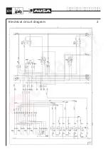
Страница 106: ...Electrical circuit diagram 2 C 400 H C 400 HI C 400 H x4 C 400 HI x4 C 500 H C 500 HI C 500 H x4 C 500 HI x4 104 ...

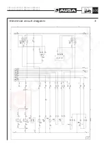
Страница 107: ...Electrical circuit diagram 3 C 400 H C 400 HI C 400 H x4 C 400 HI x4 C 500 H C 500 HI C 500 H x4 C 500 HI x4 105 ...

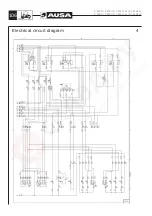
Страница 108: ...Electrical circuit diagram 4 C 400 H C 400 HI C 400 H x4 C 400 HI x4 C 500 H C 500 HI C 500 H x4 C 500 HI x4 106 ...

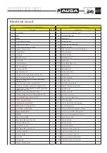
Страница 109: ...5A 2 S56 Rotating Flashing beacon switch 4 F8 4x4 not used 3rd and 4rth service solenoids sideshift or attachments fuse 7 5A 2 S57 Worklight switch 4 F9 Dash panel lights heater motor fuse 10A 1 S58 Heater motor switch 3 F10 Flashing rotating beacon and working lights fuse 25A 4 S59 4x4 switch not used 2 F11 Permanent live warning lights switch 15A 4 S60 Front windscreen wiper switch 3 F30 Starter...

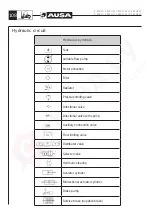
Страница 110: ... Directional valve Directional valve with spring Auxiliary connection valve Flow limiting valve Distributor valve Selector valve Hydraulic steering Actuator cylinder Bidirectional actuator cylinder Brake pump Service brake negative brake C 400 H C 400 HI C 400 H x4 C 400 HI x4 C 500 H C 500 HI C 500 H x4 C 500 HI x4 108 ...

Страница 111: ...Hydraulic circuit diagram HYDRAULIC APPLIANCES C 400 H C 400 HI C 400 H x4 C 400 HI x4 C 500 H C 500 HI C 500 H x4 C 500 HI x4 109 ...

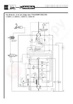
Страница 112: ...Hydraulic circuit diagram TRANSMISSION C400H C400HI C500H C500HI C 400 H C 400 HI C 400 H x4 C 400 HI x4 C 500 H C 500 HI C 500 H x4 C 500 HI x4 110 ...

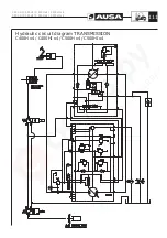
Страница 113: ...Hydraulic circuit diagram TRANSMISSION C400H x4 C400HI x4 C500H x4 C500HI x4 C 400 H C 400 HI C 400 H x4 C 400 HI x4 C 500 H C 500 HI C 500 H x4 C 500 HI x4 111 ...

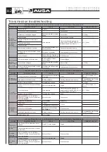
Страница 114: ...x rpm of engine High pressure limit is set too low Working pressure Working pressure ports in pump Recommended max Pressu re 345 or 410 bar Inching is seized SAUER Potentiometer linkage Pedal 0 3 bar Low trac tion power Engine does not work at nominal level or it s over Haul of accelerator lever Engine 85 95 max rpm of engine Low load pressure Load pressure Pressure intake with a gauge on pump spo...

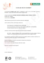
Страница 115: ...ompatibility Directive 2004 108 EC Sound level Directives of machinery used outdoors 2000 14 EC and 2005 88 EC Exhaust emissions Directives 97 68 and 2004 26 and also it conforms with the following harmonized European Standards EN 1726 1 Safety of industrial trucks Self propelled trucks up to and including 10 000 kg capacity and industrial tractors with a drawbar pull up to and including 20 000 N ...

Страница 116: ......

Страница 117: ......

Страница 118: ......

Отзывы: