208
2467S–AVR–07/09
ATmega128
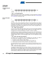
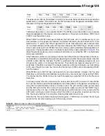
TWI Data Register –
TWDR
In Transmit mode, TWDR contains the next byte to be transmitted. In receive mode, the TWDR
contains the last byte received. It is writable while the TWI is not in the process of shifting a byte.
This occurs when the TWI interrupt flag (TWINT) is set by hardware. Note that the Data Register
cannot be initialized by the user before the first interrupt occurs. The data in TWDR remains sta-
ble as long as TWINT is set. While data is shifted out, data on the bus is simultaneously shifted
in. TWDR always contains the last byte present on the bus, except after a wake up from a sleep
mode by the TWI interrupt. In this case, the contents of TWDR is undefined. In the case of a lost
bus arbitration, no data is lost in the transition from Master to Slave. Handling of the ACK bit is
controlled automatically by the TWI logic, the CPU cannot access the ACK bit directly.
• Bits 7..0 – TWD: TWI Data Register
These eight bits constitute the next data byte to be transmitted, or the latest data byte received
on the Two-wire Serial Bus.
TWI (Slave) Address
Register – TWAR
The TWAR should be loaded with the 7-bit slave address (in the seven most significant bits of
TWAR) to which the TWI will respond when programmed as a slave transmitter or receiver, and
not needed in the master modes. In multimaster systems, TWAR must be set in masters which
can be addressed as slaves by other masters.
The LSB of TWAR is used to enable recognition of the general call address ($00). There is an
associated address comparator that looks for the slave address (or general call address if
enabled) in the received serial address. If a match is found, an interrupt request is generated.
• Bits 7..1 – TWA: TWI (Slave) Address Register
These seven bits constitute the slave address of the TWI unit.
• Bit 0 – TWGCE: TWI General Call Recognition Enable Bit
If set, this bit enables the recognition of a General Call given over the Two-wire Serial Bus.
Using the TWI
The AVR TWI is byte-oriented and interrupt based. Interrupts are issued after all bus events, like
reception of a byte or transmission of a START condition. Because the TWI is interrupt-based,
the application software is free to carry on other operations during a TWI byte transfer. Note that
the TWI Interrupt Enable (TWIE) bit in TWCR together with the Global Interrupt Enable bit in
SREG allow the application to decide whether or not assertion of the TWINT flag should gener-
ate an interrupt request. If the TWIE bit is cleared, the application must poll the TWINT flag in
order to detect actions on the TWI bus.
When the TWINT flag is asserted, the TWI has finished an operation and awaits application
response. In this case, the TWI Status Register (TWSR) contains a value indicating the current
state of the TWI bus. The application software can then decide how the TWI should behave in
the next TWI bus cycle by manipulating the TWCR and TWDR Registers.
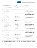
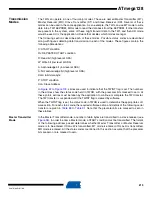
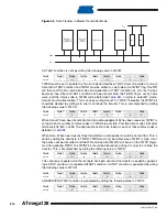
is a simple example of how the application can interface to the TWI hardware. In this
example, a master wishes to transmit a single data byte to a slave. This description is quite
Bit
7
6
5
4
3
2
1
0
TWD7
TWD6
TWD5
TWD4
TWD3
TWD2
TWD1
TWD0
TWDR
Read/Write
R/W
R/W
R/W
R/W
R/W
R/W
R/W
R/W
Initial Value
1
1
1
1
1
1
1
1
Bit
7
6
5
4
3
2
1
0
TWA6
TWA5
TWA4
TWA3
TWA2
TWA1
TWA0
TWGCE
TWAR
Read/Write
R/W
R/W
R/W
R/W
R/W
R/W
R/W
R/W
Initial Value
1
1
1
1
1
1
1
0
Содержание ATmega128
Страница 384: ...vi 2467S AVR 07 09 ATmega128 Rev 2467C 02 02 377 Table of Contents i...
Страница 385: ...vii 2467S AVR 07 09 ATmega128...

