140
2467S–AVR–07/09
ATmega128
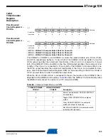
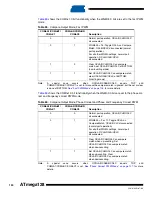
• Bit 5 – TICIE1: Timer/Counter1, Input Capture Interrupt Enable
When this bit is written to one, and the I-flag in the Status Register is set (interrupts globally
enabled), the Timer/Counter1 Input Capture interrupt is enabled. The corresponding interrupt
vector (
) is executed when the ICF1 flag, located in TIFR, is set.
• Bit 4 – OCIE1A: Timer/Counter1, Output Compare A Match Interrupt Enable
When this bit is written to one, and the I-flag in the Status Register is set (interrupts globally
enabled), the Timer/Counter1 Output Compare A Match Interrupt is enabled. The corresponding
interrupt vector (see “Interrupts” on page 60) is executed when the OCF1A flag, located in TIFR,
is set.
• Bit 3 – OCIE1B: Timer/Counter1, Output Compare B Match Interrupt Enable
When this bit is written to one, and the I-flag in the Status Register is set (interrupts globally
enabled), the Timer/Counter1 Output Compare B Match Interrupt is enabled. The corresponding
interrupt vector (see “Interrupts” on page 60) is executed when the OCF1B flag, located in TIFR,
is set.
• Bit 2 – TOIE1: Timer/Counter1, Overflow Interrupt Enable
When this bit is written to one, and the I-flag in the Status Register is set (interrupts globally
enabled), the Timer/Counter1 overflow interrupt is enabled. The corresponding interrupt vector
(see “Interrupts” on page 60) is executed when the TOV1 flag, located in TIFR, is set.
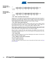
Extended
Timer/Counter
Interrupt Mask
Register – ETIMSK
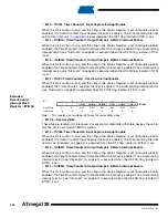
Note:
This register is not available in ATmega103 compatibility mode.
• Bit 7:6 – Reserved Bits
These bits are reserved for future use. For ensuring compatibility with future devices, these bits
must be set to zero when ETIMSK is written.
• Bit 5 – TICIE3: Timer/Counter3, Input Capture Interrupt Enable
When this bit is written to one, and the I-flag in the Status Register is set (interrupts globally
enabled), the Timer/Counter3 Input Capture Interrupt is enabled. The corresponding interrupt
vector (see “Interrupts” on page 60) is executed when the ICF3 flag, located in ETIFR, is set.
• Bit 4 – OCIE3A: Timer/Counter3, Output Compare A Match Interrupt Enable
When this bit is written to one, and the I-flag in the Status Register is set (interrupts globally
enabled), the Timer/Counter3 Output Compare A Match Interrupt is enabled. The corresponding
interrupt vector (see “Interrupts” on page 60) is executed when the OCF3A flag, located in
ETIFR, is set.
• Bit 3 – OCIE3B: Timer/Counter3, Output Compare B Match Interrupt Enable
When this bit is written to one, and the I-flag in the Status Register is set (interrupts globally
enabled), the Timer/Counter3 Output Compare B Match Interrupt is enabled. The corresponding
interrupt vector (see “Interrupts” on page 60) is executed when the OCF3B flag, located in
ETIFR, is set.
Bit
7
6
5
4
3
2
1
0
–
–
TICIE3
OCIE3A
OCIE3B
TOIE3
OCIE3C
OCIE1C
ETIMSK
Read/Write
R
R
R/W
R/W
R/W
R/W
R/W
R/W
Initial Value
0
0
0
0
0
0
0
0
Содержание ATmega128
Страница 384: ...vi 2467S AVR 07 09 ATmega128 Rev 2467C 02 02 377 Table of Contents i...
Страница 385: ...vii 2467S AVR 07 09 ATmega128...

