201
2467S–AVR–07/09
ATmega128
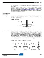
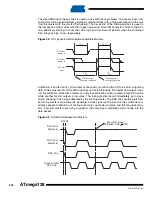
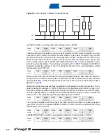
Figure 90.
Data Packet Format
Combining Address
and Data Packets Into
a Transmission
A transmission basically consists of a START condition, a SLA+R/W, one or more data packets
and a STOP condition. An empty message, consisting of a START followed by a STOP condi-
tion, is illegal. Note that the Wired-ANDing of the SCL line can be used to implement
handshaking between the master and the slave. The slave can extend the SCL low period by
pulling the SCL line low. This is useful if the clock speed set up by the master is too fast for the
slave, or the slave needs extra time for processing between the data transmissions. The slave
extending the SCL low period will not affect the SCL high period, which is determined by the
master. As a consequence, the slave can reduce the TWI data transfer speed by prolonging the
SCL duty cycle.
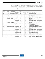
shows a typical data transmission. Note that several data bytes can be transmitted
between the SLA+R/W and the STOP condition, depending on the software protocol imple-
mented by the application software.
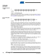
Figure 91.
Typical Data Transmission
Multi-master Bus
Systems,
Arbitration and
Synchronization
The TWI protocol allows bus systems with several masters. Special concerns have been taken
in order to ensure that transmissions will proceed as normal, even if two or more masters initiate
a transmission at the same time. Two problems arise in multi-master systems:
•
An algorithm must be implemented allowing only one of the masters to complete the
transmission. All other masters should cease transmission when they discover that they
have lost the selection process. This selection process is called arbitration. When a
contending master discovers that it has lost the arbitration process, it should immediately
switch to slave mode to check whether it is being addressed by the winning master. The fact
that multiple masters have started transmission at the same time should not be detectable to
the slaves, i.e., the data being transferred on the bus must not be corrupted.
•
Different masters may use different SCL frequencies. A scheme must be devised to
synchronize the serial clocks from all masters, in order to let the transmission proceed in a
lockstep fashion. This will facilitate the arbitration process.
1
2
7
8
9
Data MSB
Data LSB
ACK
Aggregate
SDA
SDA from
Transmitter
SDA from
Receiver
SCL from
Master
SLA+R/W
Data Byte
STOP, REPEATED
START or Next
Data Byte
1
2
7
8
9
Data Byte
Data MSB
Data LSB
ACK
SDA
SCL
START
1
2
7
8
9
Addr MSB
Addr LSB
R/W
ACK
SLA+R/W
STOP
Содержание ATmega128
Страница 384: ...vi 2467S AVR 07 09 ATmega128 Rev 2467C 02 02 377 Table of Contents i...
Страница 385: ...vii 2467S AVR 07 09 ATmega128...


