background image

Installation and

commissioning  

instructions

for professionals

to be kept by the user

for future reference
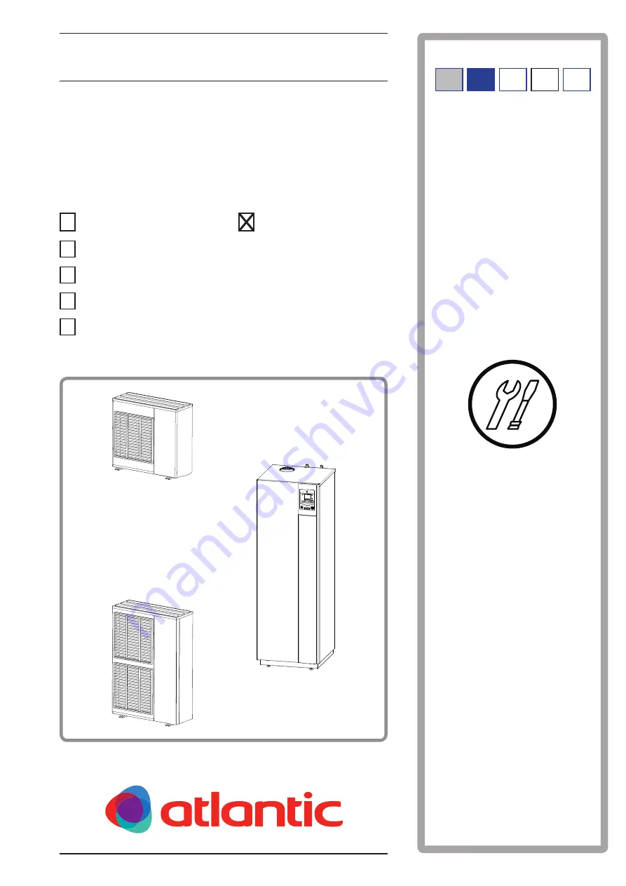
Outdoor unit

Hydraulic unit

WOYG112LCT

024200

WOYG140LCT

WOYK112LCT

WOYK140LCT

WOYK160LCT

Air/water heat pump

with integrated gas burner,

split, 2 services

Document n° 1485-

9

 ~ 

26

/0

7

/2013

alféa hybrid duo gas

atlantic-comfort.com

The specifications of this equipment may 

be modified without prior notice

Non-contractual document.

FR EN IT DE EN

ES PT

Содержание 024200

Страница 1: ...ulic unit WOYG112LCT 024200 WOYG140LCT WOYK112LCT WOYK140LCT WOYK160LCT Air water heat pump with integrated gas burner split 2 services Document n 1485 9 26 07 2013 alféa hybrid duo gas atlantic comfort com The specifications of this equipment may be modified without prior notice Non contractual document FR EN IT DE EN ES PT ...

Страница 2: ... capable of handling refrigerating fluids according to environmental legislation a heating engineer Certificate of conformity The use of a gas boiler requires a Certificate of Conformity signed by local authorities Installation and commissioning instructions 1485 EN Heat pump alféa hybrid duo gas 2 ...

Страница 3: ... Filling the installation with gas 27 Commissioning procedure 27 Sealing test 28 Additional charge 29 Collect the refrigerant fluid in the outdoor unit 29 Connecting the heating circuit and the domestic circuit 30 General 30 Rinsing the installation 30 Filling and draining the installation 31 Connection to an underfloor heating circuit 31 Connection to a fan coil circuit 31 Connection to the domes...

Страница 4: ...display 48 Water logic 48 Setting 48 Electrical wiring diagrams 62 Regulation parameters 50 General 50 Setting the parameters 50 List of the function lines settings diagnosis state 50 Checks before commissioning 41 Hydraulic circuit 41 Gas circuit 41 Electric circuit 41 Commissioning the heat pump 41 Starting the gas generator to check the combustion 42 Heating installation with radiators 42 Heati...

Страница 5: ...140 LCT 700143 alféa hybrid duo gas 16 three phase 522186 WOYK 160 LCT 700163 1 2 Optional equipment Optional equipment 2 circuit kit ref 074012 to connect 2 heating circuits or an under floor heating circuit Class A pump kit ref 074013 DHW expansion kit ref 074026 Chimney adaptor 80 125 ref 073423 for a B23 type connection Room thermostat T37 code 075308 Room thermostat T55 code 073951 Wireless r...

Страница 6: ...densation return 30 C kW 24 8 Minimum useful power 80 60 C kW 5 5 Minimum calorific flow rate kW 5 7 Electrical characteristics Voltage 50 HZ V 230 400 Maximum current of the appliance A 22 25 8 5 9 5 10 5 Nominal current A 11 4 14 2 3 7 4 8 5 5 Actual power absorbed by the fan W 2 x 110 2 x 10⁴ by the heat flow pump circulators max gas generator W 132 93 Maximum power absorbed by the outdoor unit...

Страница 7: ... conical 3 9 mm Combustion products Smoke temperature minimum maximum C 35 70 Smoke mass flow rate minimum maximum g s 2 87 11 9 Concentric horizontal or vertical room sealed turbo pipe Smoke air aspiration tube diameter C13 C33 mm 80 125 Smoke tube diameter C53 mm 80 Maximum authorised straight line length excluding terminal m 11 Loss of charge by elbow 90 45 m 1 0 5 Compatible terminal and mater...

Страница 8: ...de view 31 77 900 330 12 9 400 650 Air Orifice d écoulement Ø 20 4 trous Ø 10 Vue de dessus Vue de face Vue de dessous Vue de côté 21 1290 147 170 196 370 99 3 8 5 8 Air Air Outdoor unit hybrid duo gas 11 single phase model hybrid duo gas 14 single phase model Front view Top view Side view Bottom view 4 holes Flow opening Installation and commissioning instructions 1485 EN Heat pump alféa hybrid d...

Страница 9: ...99 Heating flow Ø 26x34 M DHW Ø 20x27 M Cold water Ø 20x27 M Heating return Ø 26x34 M Gas Ø 20x27 M Hydraulic module Dimensions of the hydraulic module see figure 15 page 18 Rear view Side view Chimney connection Ø 80 125 Installation and commissioning instructions 1485 EN 9 Heat pump alféa hybrid duo gas ...

Страница 10: ...re 5 Ohmic value of the sensors outdoor unit 20 10 0 10 20 30 40 50 60 70 80 90 100 110 120 130 10000 1000 100 10 1 Compressor Discharge Condensation Evaporator outlet Evaporator middle Compressor carter Outdoor Temperature C Ohmic value kΩ figure 3 Hydraulic pressures and flow rates available 0 100 200 300 400 500 600 mbar 0 4 0 5 0 6 0 7 0 8 0 9 1 1 1 1 2 1 3 1 4 1 5 1 6 1 7 1 8 1 9 2 m3 h 1 2 3...

Страница 11: ...ated 11 Refrigerating connection taps flare connector with protective cover 12 Condensate basin with drain hole 13 High performance exchange surface evaporator anti corrosion treated hydrophilic aluminium fins and grooved copper tubes 14 Solenoid valve for injection of liquid 15 Electronic pressure regulator for injection of liquid 16 Inverter compressor acoustically and thermally insulated with l...

Страница 12: ...10 Safety valve Automatic drain tap 11 18l expansion vessel maintenance position 12 Gas valve 13 Fan 14 Gas condensing exchanger Gaz EG 15 Pressure flap 16 Disconnectable no return valve 17 Inspection trap 18 Titanium anode ACI 19 Adjustable feet 20 Hot water sensor 21 Heat pump output sensor common sensor 22 Heat pump return sensor 23 Condensation sensor 24 EG output sensor 25 EG return sensor 26...

Страница 13: ...mbient sensor optional provides a corrective action to the water logic The hydraulic module is equipped gas generator which operates at the request of the regulator to provide additional heating during the colder periods to reach the DHW comfort value to provide a relay during Peak rate days load shedding or EJP function Priority is given to the operation of the heat pump When the heat pump is not...

Страница 14: ...h monitors the hydraulic pressure If the pressure is lower than 0 5 bars Safety 0 8 bars Power reduction and information on the display Miscellaneous Start and return temperature monitoring Smoke temperature monitoring Operating principle of the domestic hot water DHW DHW production takes priority over heating Two domestic hot water DHW temperatures may be set comfort temperature line 1610 at 55 C...

Страница 15: ... immediately returned to the vertical position 1 3 2 4 1 Elbow for condensate evacuation 2 Plugs x2 depending on model 4 Allen wrench to open valves figure 11 Accessories supplied with the external unit Outdoor sensor to detect the outdoor temperature figure 12 Accessories provided with the hydraulic module 8 5 6 7 5 2 2 3 Containment of refrigerant circuits All refrigerant circuits fear contamina...

Страница 16: ...e phase model figure 13 Prefer a sunny location sheltered from strong and cold dominant winds The appliance must be completely accessible for subsequent installation and maintenance work figure 13 Ensure that the connections can be made easily with the hydraulic module The outdoor unit can be exposed to the weather however avoid installing it in places where it will 1000 mm ou plus 200 mm 300 mm 2...

Страница 17: ...t using screw and spring or split washers to ensure they do not come loose Warning In regions with heavy snowfall if the outdoor unit s entrance and exit are blocked by snow it may be difficult to heat up and may probably cause a breakdown Build an awning or place the appliance on a tall support local configuration Put the appliance on a solid support to minimise impact and vibration Do not place ...

Страница 18: ... blockable cross section of at least 100 cm2 positioned in the upper part and opening directly outdoors see figure 15 The air renewal volume must be at least P kW x 2 m3 h i e 48 m3 h The warranty on the heater will not cover any installation of the appliance in a chlorine rich atmosphere hairdressers launderette etc or any other corrosive vapours Be careful of the presence of inflammable gas clos...

Страница 19: ...ough an opening of at least 100 cm 2 7 Chimney connection pipe B23 B23P The connection pipe must comply with the regulations in force The cross section of the connection pipe must not be smaller than the outlet nozzle of the appliance The connection pipe must be removable The evacuation nozzle is to be connected to the pipe so that there are no leaks Reminder The chimney adaptor provided must be u...

Страница 20: ...40 m away from any opening windows and 0 60 m away from any ventilation air intake openings If the evacuation leads onto a public or private road it must be protected from any external interventions likely to harm its normal operation When the terminal leads out over a horizontal surface ground terrace a minimum distance of 0 30 m must be respectedbetweenthebaseoftheterminalandthissurface Recommen...

Страница 21: ... type connection with 3 90 elbows L1 L2 L3 3 x 1 m 11 m Example of C33 type connection with 2 45 elbows L1 L2 L3 2 x 0 5 m 11 m Example of C33 type connection with Rénolux system entry into wall with 2 90 elbows and 2 30 offsets L1 L2 2 x 1 m 2 x 0 3 m 11 m entry into wall with 2 30 offsets L1 L2 2 x 0 3 m 11 m RT Telescopic pipe T terminal max 1 m Rénolux system for adaptation to the existing eva...

Страница 22: ... parts and the finishing plate The chimney pipe s internal dimension must be at least equal to 140 mm in diameter or side Check the pipe s seal and range Cleaning the evacuation pipe before installation The chimney must be cleaned to remove all imperative and soot that may damage the appliance Make sure that the evacuation pipe s intake and outlet connections are perfectly sealed 2 8 3 Separate ai...

Страница 23: ... 4 m 0 4 m 0 4 m L1 L1 0 6 m mini 0 6 m mini 0 3 m 0 4 m 2 m 0 4 m 2 m 0 3 m 0 4 m 0 4 m 0 4 m 1 2 m 0 3 m 0 15 m 0 6 m 0 6 m A Leaf I Leaf M Air inlet E Pinion with leaf B Air inlet J Incoming angle N Area surrounding a smoke pipe with natural draft F Blind pinion C Dormer K Leaf G Roof rib D Dormer L Leaf H Anti snow Legend Prohibited areas Areas that are not recommended Authorised areas Install...

Страница 24: ...dity that can harm the operation of the appliance In general take all precautions to avoid humidity penetrating into the appliance Thermally insulate the gas and liquid pipe to avoid all condensation Use insulating sleeves that resist temperatures of over 90 C In addition if the level of humidity where the refrigerating pipes risks exceeding 70 protect them with insulating sleeves Use a 15 mm thic...

Страница 25: ...his can cause the pipe to split hardening of the metal 2 9 5 Connecting the flare connections Connections must be made the day of the filling the installation with gas see para 2 10 page 27 Pay special attention to the position of the tube aligned with its connector to avoid damaging the thread A correctly aligned connector can be fitted easily by hand without much force being required The refrige...

Страница 26: ... Outdoor unit Heat pump model alféa hybrid gas single phase three phase gas liquid Raccords unité extérieure 5 8 3 8 Liaisons frigorifiques Diameter D1 5 8 D2 3 8 Minimum length L 5 Maximum length L 15 20 Difference in height D 15 20 Hydraulic module connectors 5 8 3 8 without additional charge of R410A Taking into account the potential additional charge of refrigerating fluid R410A see 2 10 3 pag...

Страница 27: ...the vacuum pump Connect the vacuum pump with the vacuum gauge according to the scheme Pump down during 3 minutes After 3 minutes the pump reaches its threshold value and the vacuum gauge needle does not move Compare the obtained pressure with the value of the table Depending on the temperature this pressure must be less than the value indicated in the table If it s not the case replace the gasket ...

Страница 28: ...9 9 0 015 15 0 020 20 figure 25 Connexion of the hose on the Gaz valve Let the pump continue to operate for another 30 minutes minimum after reaching the vacuum Close the Manifold valve and then stop the vacuum pump without disconnecting any of the hoses in place If the outdoor temperature is between 5 and 10 C use method 3 empty see ANNEX 2 Remove the access plugs A from the valve controls If an ...

Страница 29: ...the R410A set of pressure gauges Always add charge in liquid phase Do not exceed the maximum length or difference in height DIP SW Interface board LED2 green LED1 red figure 26 Position of the DIP switches and the LEDs on hydraulic module interface board figure 27 Gas bottle R410A R410A Gas Liquid 2 10 4 Collect the refrigerant fluid in the outdoor unit Carry out the following procedures to collec...

Страница 30: ...nhibitor in the proportions recommended by its manufacturer Refer to the Domestic hot water and heating treatment section in our price catalogue It is also necessary to ensure that the water treated does not become aggressive 2 11 2 Rinsing the installation Before connecting the hydraulic module to the installation rinse the heating system correctly to eliminate the particles that could compromise...

Страница 31: ...o this circuit minimum capacity 50 litres figure 29 Hydraulic module drain taps P Manual drain tap P Manual drain tap A Automatic drain tap 2 11 6 Connection to the domestic circuit Place a safety group with a valve calibrated to 7 bar on the cold water inlet and connect an evacuation pipe leading to the drain Run the safety group according to the manufacturer s recommendations Connect the safety ...

Страница 32: ...e below Position the diaphragm in the gasket s throat Restore the connector Carry out a combustion check see para Setting the combustion parameters during a gas check page 43 Gas Diaphragm marker CO2 at min CO2 at max G 20 20 8 to 9 8 5 to 9 5 G 25 no diaphragm 8 to 9 8 5 to 9 5 G 31 conical 9 5 to 10 5 10 to 11 Paste the gas setting label provided with the conversion kit 2 14 Connection of the fu...

Страница 33: ... wires The earth connection and its continuity must be ensured Connection to the spring terminal blocks Rigid wire A Rigid wire is always preferable for fixed installations especially in buildings Always choose a wire that complies with current standards NF C 15 100 in particular Bare the end of the wire over a length of around 25 mm With round nosed pliers make a loop with a diameter that corresp...

Страница 34: ... breaker calibre hybrid duo 11 5865 W 5 x 2 5 mm 20 A hybrid duo 14 6555 W hybrid duo 16 7245 W Inter connection between the outdoor unit and the hydraulic module The hydraulic module is powered by the outdoor unit via a cable 4x1 5 mm phase neutral earth communication bus figure 34 General diagram of the electrical connections for a simple installation 1 heating circuit Outdoor sensor cable 2x0 5...

Страница 35: ...ver Hook 4places Terminal block Terminal block Interconnection between the outdoor unit and the hydraulic unit General electrical supply Use the cable clamps to avoid any accidental discon nection of the conductive wires Use the attachment plate to hold the cables against the insulating plate item 1 to 3 figure 37 Attach the cables so that they are not in contact with the pipes and the valves Cove...

Страница 36: ... to the terminal block of the outdoor unit Remove the screws and push downwards Remove the front panel Terminal block figure 39 Access to the terminal block of the outdoor unit 1 INDOORUNIT POWER 2 3 L1 L2 L3 N Terminal block Inter connection between outdoor unit and hydraulic module General electrical power supply figure 40 Finalising of the connection of the outdoor unit Cable clamp Cables power...

Страница 37: ...lation board RVS manages the whole appliance and regulates the different heating circuits 2 COM interfaces OCI 345 provide the communication between the 2 LMS and RVS boards and the transmission of the climate data slope temperatures Interface board provides the link with the outdoor unit Connection terminal Grommets power Grommet sensors Do not fit the sensor wires and the power supply wires in p...

Страница 38: ... L N 2 4 L N LN 1 2 3 4 5 6 Outdoor unit single phase Hydraulic module 230 V electrical power supply towards outdoor contact device red blue brown green yellow Inter connection between outdoor unit and hydraulic module Single phase model 1 2 3 4 5 6 1 2 3 L1 L2 L3 N L1 L2 L3 N Outdoor unit three phase Hydraulic module 400 V electrical power supply towards outdoor contact device red blue brown gree...

Страница 39: ...mperature of the air outdoors Connect the external sensor to the LMS board s X5b remote connector 2 17 Room thermostat and or Room control unit The ambient thermostat the central ambient unit is optional Consult the assembly instructions on the packaging The sensor must be installed in the living area on an open wall It is to be installed so that it is easily accessible Avoid sources of direct hea...

Страница 40: ...peak not concerned External fault Outdoor contact device faults load shedder energy meter If the command does not supply a potential free contact the contact must be relayed to obtain equivalent wiring In all cases refer to the instructions for the external parts load shedder energy meters for the wiring Option T75 Terminal 3 of the central ambient unit T75 does not need to be connected central am...

Страница 41: ...of the electrical power supply is respected When put into service and every time that the Start Stop switch is switched off and then back on the outdoor unit requires approximately 4 min to start up even if the regulation has demanded heating The display may show error 370 when starting Do not worry the communication will be reestablished between the outdoor unit and the hydraulic module after a f...

Страница 42: ...e initial configuration 7143 Off 5 Reconnect the user interface layer to the RVS X50 Initialising the interface takes a few minutes 6 Reactivate the DHW function if necessary 3 3 2 Heating installation with 1 underfloor heating circuit Close the underfloor heating circuit mixer valve manually The energy created during this setting period must be dissipated over the domestic circuit draw off some d...

Страница 43: ... CO2 rate by setting the gas rate on the burner screw item R1 figure 49 Adjust the parameter 7145 Enter the value required 0 operation at min The burner runs at MIN rate Check the CO2 rate see table opposite If necessary adjust the pressure regulator setpoint gently screw item R2 figure 49 Check the settings at MAX rate Modify if necessary When the settings are complete Set the parameter in the in...

Страница 44: ...hen putting into service after a reset of around 3 minutes the user language needs to be set Press OK Select the user Interface menu Select the language Select the language English Deutsch Français Italiano Nederlands Español Português Dansk If the installation has a single circuit zone 2 is active CC2 In the case of 2 heating circuits Choose the central ambient unit s assignment ambience applianc...

Страница 45: ... ...

Страница 46: ...om thermostat option figure 51 C Auto Auto ESC OK 0 4 8 12 16 20 24 1 2 3 4 5 6 7 8 11 5 2 10 11 Room control unit T75 T78 Room thermostat T55 T58 1 2 3 4 5 6 7 8 9 User interface Installation and commissioning instructions 1485 EN Heat pump alféa hybrid duo gas 46 ...

Страница 47: ...ating according to the heating programme automatic summer winter switching Permanent comfort temperature Permanent reduced temperature Standby operation with antifreeze protection provided that the electrical power supply of the heat pump is not interrupted 6 Display information Miscellaneous information see page 70 Reading the error codes see page 65 Information on maintenance special operation 7...

Страница 48: ... ambient setpoint of 20 C The water logic slope parameter 720 determines the impact of variations in outdoor temperature on the variations in heating start temperature The higher the slope the less the reduction in outdoor temperature will create a significant increase in the heating circuit water start temperature The shift in water logic parameter 721 modifies the start temperature of all the cu...

Страница 49: ...0 70 20 15 10 5 5 10 4 5 4 5 20 0 10 30 0 30 Heating start temperature C Outdoor temperature C Translation Water logic slope 0 5 figure 53 Slope of the heating curve line 720 2 4 3 75 3 5 3 25 2 5 2 25 2 1 25 1 5 1 75 1 0 75 0 5 0 25 3 2 75 20 15 10 5 0 5 10 15 20 70 60 50 40 30 20 Heating start temperature C Outdoor temperature C Heat pump gas generator operation Traditional radiator Low temperat...

Страница 50: ...nd user Commissioning Specialist OEM Time of day and date Hours minutes 1 User interface Day Month 2 CC1 time programme Year 3 Start of summer time 4 01 01 31 12 End of summer time 5 Line Function Setting range or display Setting increment Basic setting Time and date 1 U Hours minutes 00 00 23 59 1 2 U Day Month 01 01 31 12 1 3 U Year 1900 2099 1 5 S Start of summer time Day Month 01 01 31 12 1 25...

Страница 51: ...ase Off end 00 00 10 min 22 00 523 U 2nd phase On start 00 00 10 min 524 U 2nd phase Off end 00 00 10 min 525 U 3rd phase On start 00 00 10 min 526 U 3rd phase Off end 00 00 10 min 536 U Standard values No Yes No Yes OK The standard values saved in the regulator replace and cancel the personalised heating programmes Your personal settings are therefore lost Timer programme 4 DHW The DHW timer prog...

Страница 52: ...ter heating limits 8 C 30 C 0 5 C 18 C When the average of the outside temperatures over the past 24 hours reaches 18 C the regulator switches off the heating as an economy measure During summer mode the display shows Eco This function is only active in automatic mode 740 S Flow temp setpoint min for fan convector 8 C Flow temp setpoint max 1 C 8 C 741 S Flow temp setpoint max Flow temp setpoint m...

Страница 53: ...e slab drying temperature This temperature remains fixed The concrete slab drying programme stops automatically after running for 25 days 856 I Current drying day 0 32 0 857 I Terminated drying days 0 32 0 900 S Change of regime None Protection mode Reduced Comfort Automatic 1 Reduced Operating mode at end of concrete slab drying period Please comply with the standards and instructions of the manu...

Страница 54: ...mitation 0 5 4 C 0 5 C 0 5 C As soon as the room temperature Setpoint line 1010 ex 20 C Room temperature limitation setpoint line 1060 ex 0 5 C 20 5 C The heat pump is stopped It restarts when the room temperature falls below the setpoint in the example Room temperature 20 0 C 1080 S Quick setback Off Down to reduced setpoint Down to frost prot setpoint Off 1090 S Maximum optimisation on switch on...

Страница 55: ... S Intervals for the anti legionella cycles 1 to 7 1 day 7 1642 S Weekday anti legionella cycle run Monday Tuesday Saturday Swimming pool Only with swimming pool kit option 2056 U Generator heating setting 8 35 C 22 C Heat pump HP 2803 S Overrun time cond pump 8 240 s 1 s 240s 2843 S Compressor off time min 0 120 min 1 C 8 min 2844 S Switch off temp max 8 100 C 1 C 65 C 2862 S Locking time stage 2...

Страница 56: ... Summer 5061 S Release of electrical resistance 24h day Release of DHW Programme 4 DHW Release of DHW 5093 S Not used Installation configuration 5700 I Pre settings 1 2 3 10 1 10 For all installation configurations the preset is 10 5710 S Heating circuit 1 Off On Off For a simple installation 1 radiator circuit only Stop With 2 circuit kit option 2 circuits or 1 underfloor heating circuit On 5711 ...

Страница 57: ...nual Emergency mode is not active when a fault occurs Emergency mode OFF Automatic Emergency mode is active when a fault occurs Emergency mode ON 7150 I Outside temperature simulation 50 50 C 0 5 Inputs outputs test 7700 I Relay test 0 This consists of instructing the regulator s relays one by one and checking their outputs This enables you to check that the relays are working and that the cabling...

Страница 58: ...put EX2 Tariffs day night 0 230 V 7913 I Input EX3 External fault 0 230 V 7973 I Sensor temperature BX31 Mixed circuit temp 28 350 C 7974 I Sensor temperature BX32 28 350 C 7975 I Sensor temperature BX33 28 350 C 7976 I Sensor temperature BX34 Swimming pool exchanger temperature 28 350 C 7977 I Sensor temperature BX35 28 350 C 7978 I Sensor temperature BX36 28 350 C 7996 I Contact status H33 Open ...

Страница 59: ...ximum outside temperature Reset no yes 50 50 C 8703 I Attenuated outside temperature Reset no yes 50 50 C This is the average of the outside temperature over a 24 hour period This value is used for automatic Summer Winter switchover line 730 8704 I Mixed outside temperature 50 50 C The mixed outside temperature is a combination of the current outside temperature and the average outside temperature...

Страница 60: ...re 0 140 C Common flow temperature setpoint 8957 I Common flow setpoint refrigeration 0 140 C 8980 I Not used 8981 I Not used 9031 I Relay output QX1 Off On On 9032 I Relay output QX2 Off On On 9033 I Relay output QX3 Off On Off 9034 I Relay output QX4 Off On Off 9035 I Relay output QX5 Off On Off 9050 I Relay output QX21 module 1 Off On Not concerned 9051 I Relay output QX22 module 1 Off On Not c...

Страница 61: ... Installation and commissioning instructions 1485 EN 61 Heat pump alféa hybrid duo gas ...

Страница 62: ...l Fan motor 1 upper Fan motor 2 lower Option connector Refer to the technical manual Fuse Fuse Power source 230 V Interconnection between the outdoor unit and the hydraulic unit F4 T 5A 250 V F2 T 3 15A 250 V Fuse 10A Relay Diode bridge Terminal Earth Earth Terminal Terminal Compressor Active Filter Module Printed Circuit Board Main Printed Circuit Board Disply Printed Circuit Board Filter Thermis...

Страница 63: ...l Temp sensor Back flow Temp sensor Evaporator output Temp sensor Outdoor Temp sensor Compressor Pressure switch Fan reactor 4 channel valve Re injection coil Pressure regulator coil Fan 1 motor upper Fan 2 motor lower Option connector Fuses Electrical power supply 3 phases 400 V Inter connection between outdoor unit and hydraulic module F3 10A 250 V F2 3 15A 250 V F1 5A 250 V Reactors Terminal bl...

Страница 64: ...a X1a X1d X1e X18a X1c X4a Carte régulation gaz Carte interface Carte régulation PAC X11 X7b X30 Brûleur Départ Commun 0 I 1 2 3 4 5 L N COM L M M REV 01 CN18 CN7 CN30 CN8 CN6 CN9 CN16 CN22 CN1 Connections on the heat pump regulator accessories and options see figure 45 page 40 Connection to the terminal see figure 43 page 38 Pressure sensor Smoke Return Start Fan Condensation sensor Interface boa...

Страница 65: ...he red button on the side of the control panel see figure 60 Note An anomaly on the outdoor unit may case an error signal the Err light comes on In this case the domestic hot water will be produced the heating will be stopped Alert the heating engineer Hydraulic module Heat pump regulator faults RVS visible on the digital display Error number Error description Error position Heat pump operation de...

Страница 66: ... shunt connector 117 Water pressure too high Appliance continues to operate Water pressure too high or false contact Adjust the heating network s water pressure Check the sensor cabling 118 Water pressure too low Appliance continues to operate Water pressure 0 8 bars or false contact 119 Min water pressure safety function activated Shutdown of the appliance Restart when the problem disappears Wate...

Страница 67: ...r centre 7 Flashes 4 Flashes Error on outdoor temperature sensor 7 Flashes 7 Flashes Error on radiator temperature sensor inverter Error on radiator temperature sensor P F C 7 Flashes 8 Flashes Error on pressure regulator temperature sensor 8 Flashes 4 Flashes Error on compressor current 8 Flashes 6 Flashes Error on pressure switch sensor Error on pressure sensor 9 Flashes 4 Flashes Current sensor...

Страница 68: ...11 Flashes Discharge temperature protection permanent stoppage 12 Flashes Compressor temperature protection permanent stoppage 13 Flashes Current trip permanent stoppage 14 Flashes Detection of compressor position error permanent stoppage 15 Flashes Compressor start up error permanent stoppage 16 Flashes Fan motor 1 error permanent stoppage 17 Flashes Fan motor 2 error permanent stoppage 18 Flashe...

Страница 69: ...s Error on exchanger temperature sensor 6 Flashes Error on pressure regulator temperature sensor 7 Flashes Error on outdoor temperature sensor 8 Flashes Error on compressor temperature sensor 9 Flashes Error on radiator temperature sensor inverter 10 Flashes Error on radiator temperature sensor P F C 11 Flashes Discharge thermistor protection permanent stop 12 Flashes Discharge thermistor protecti...

Страница 70: ...temperature is reached Miscellaneous information see below Designation Line Floor drying current setpoint Current drying day Terminated drying days State heat pump 8006 State supplementary source 8022 State DHW 8003 State swimming pool 8011 State heating circuit 1 8000 State heating circuit 2 8001 State cooling circuit 1 8004 Outdoor temperature 8700 Room temperature 1 8740 Room setpoint 1 Flow te...

Страница 71: ...ust clean the turbine Do not forget to replace the O ring between the end piece and the fan Brush the burner grills gently if necessary Check the spacing and position of the electrodes figure 65 Refit all of the parts correctly Make sure that the boiler s burnt gas circuit is leakproof Check that the connectors are correctly tightened Open the gas valve drain the pipes and check the seal upstream ...

Страница 72: ...ve layer Carefully remove any scale deposits on the pocket Do not use any metal objects or chemical or abrasive products Change the inspection hatch gasket after each tank inspection Do not forget to reconnect the ACI 7 5 Checking the outdoor unit Remove any dust from the exchanger making sure you do not damage the blades Correct the wings using a comb Check that there is nothing hindering the air...

Страница 73: ...nel A open Return from the DHW tank Channel B open Return from the heating circuit 8 3 ACI check Check the polarity Check the voltage As the appliance is powered up the voltage value must be positive and be between 0 and 6 5 V in direct current 9 Values to be given to the user Explain to the user the operation of the installation heating and hot water temperature settings especially the ambient se...

Страница 74: ...2 and 23 page 19 to page 23 Refrigeration connections and checks see 2 9 Refrigerant connections page 24 and 2 10 Filling the installation with gas page 27 OK Non conforming Refrigerant circuits control Sealing respected no dust and moisture Connections between units pipe length flare tightening torque Installation of HP LP pressure switches on Gas line large pipe Evacuation compulsory Seal test w...

Страница 75: ...ion pressure temperature check Checks on the hydraulic module OK Non conforming Value After 15 minutes operation Difference in primary water T DHW priority directional valve switchover Heating operation boiler reading etc Regulation see 3 3 Configuration of the sensor central ambient unit 3 5 page 44 and or 3 6 page 44 OK Non conforming Configuration operations checks Carry out the hourly programm...

Страница 76: ...rying HC2 setting Domestic hot water 1610 comfort DHW T value DHW 1612 reduced DHW T value DHW 1620 Liberation of DHW DHW 1640 to 1642 Anti legionella cycle DHW Parameter Designation Setting Menus Boiler reading 3700 On author ext T addit gener Miscellaneous 6420 H33 input function 1 configuration 6100 ext T sensor correct configuration 6120 antifreeze on off configuration 6205 parameter reset con...

Страница 77: ...t T C ΔT condensation C Tank water inlet T C ΔT secondary C Evaporation T BP bar C Aspiration T C Overheating C Battery air inlet T C ΔT evaporation C Battery air output T C ΔT battery C Hydraulic network on hydraulic module Secondary network Underfloor heating Circulator make Type LV radiators Fan coils Domestic hot water tank type Secondary network water volume estimate L Gas exchanger combustio...

Страница 78: ... ...

Страница 79: ... ...

Страница 80: ... prior instructions Non contractual document atlantic comfort com www atlantic fr Société Industrielle de Chauffage SATC BP 64 59660 MERVILLE FRANCE RC Dunkirk Siren 440 555 886 1312 BQ 4180 Complies with Gas directives 2009 142 EC and Efficiency Directive 92 42 CEE standard EN625 EN297 Chimney flued EN483 Fan flued and EN 677 Low voltage directive 2006 95 CE and 93 68 CEE Electromagnetic compatib...

Отзывы: