


2-32
Chapter 2: Hardware information
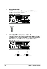
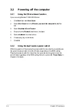
4. Front fan connectors
(4-pin FRNT_FAN1, FRNT_FAN2, FRNT_FAN3, FRNT_FAN4)
The fan connectors support cooling fans of 350 mA–740 mA (8.88 W max.)
or a total of 3.15 A–6.66 A (53.28 W max.) at +12V. Connect the fan cables to
the fan connectors on the motherboard, ensuring that the black wire of each
cable matches the ground pin of the connector.
•
DO NOT forget to connect the fan cables to the fan connectors. Insufficient
air flow inside the system may damage the motherboard components.
•
These are not jumpers! DO NOT place jumper caps on the fan connectors!
•
All fans feature the ASUS Smart Fan technology.
Содержание Z8NH-D12
Страница 1: ...Motherboard Z8NH D12 Series Z8NH D12 Z8PH D12 IFB Z8PH D12 SE QDR ...
Страница 13: ...1 Product introduction This chapter describes the motherboard features and the new technologies it supports ...
Страница 24: ...2 6 Chapter 2 Hardware information 2 2 4 Motherboard layouts Z8NH D12 ...
Страница 25: ...ASUS Z8NH D12 Series 2 7 Z8PH D12 IFB ...
Страница 26: ...2 8 Chapter 2 Hardware information Z8PH D12 SE QDR ...
Страница 56: ...2 38 Chapter 2 Hardware information ...
Страница 57: ...3 Powering up This chapter describes the power up sequence and ways of shutting down the system ...
Страница 58: ...ASUS Z8NH D12 Series Chapter summary 3 3 1 Starting up for the first time 3 3 3 2 Turning off the computer 3 4 ...
Страница 100: ...4 40 Chapter 4 BIOS setup ...
Страница 167: ...ASUS Z8NH D12 Series 6 33 8 Click your preferred options and click Finish to exit the wizard ...
Страница 175: ...ASUS Z8NH D12 Series A 3 A 1 Z8NH D12 block diagram ...
Страница 176: ...A 4 Appendix A Reference information A 2 Z8PH D12 IFB block diagram ...
Страница 177: ...ASUS Z8NH D12 Series A 5 A 3 Z8PH D12 SE QDR block diagram ...
Страница 178: ...A 6 Appendix A Reference information ...