


2-12
Chapter 2: Hardware information
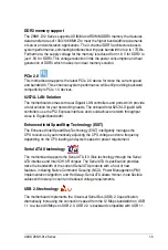
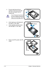
To prevent damage to the socket
pins, do not remove the PnP cap
unless you are installing a CPU.
2.
Press the load lever with your
thumb (A), then move it to the left
(B) until it is released from the
retention tab.
A
B
Load lever
Retention tab
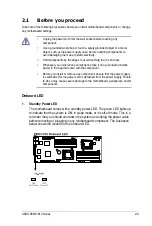
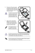
3.
Lift the load lever in the direction of
the arrow to a 135º angle.
4.
Lift the load plate with your thumb
and forefinger to a 100º angle.
Load plate
4
3
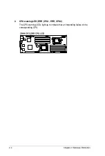
5.
Remove the PnP cap from the CPU
socket.
PnP cap
Содержание Z8NH-D12
Страница 1: ...Motherboard Z8NH D12 Series Z8NH D12 Z8PH D12 IFB Z8PH D12 SE QDR ...
Страница 13: ...1 Product introduction This chapter describes the motherboard features and the new technologies it supports ...
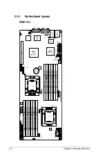
Страница 24: ...2 6 Chapter 2 Hardware information 2 2 4 Motherboard layouts Z8NH D12 ...
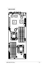
Страница 25: ...ASUS Z8NH D12 Series 2 7 Z8PH D12 IFB ...
Страница 26: ...2 8 Chapter 2 Hardware information Z8PH D12 SE QDR ...
Страница 56: ...2 38 Chapter 2 Hardware information ...
Страница 57: ...3 Powering up This chapter describes the power up sequence and ways of shutting down the system ...
Страница 58: ...ASUS Z8NH D12 Series Chapter summary 3 3 1 Starting up for the first time 3 3 3 2 Turning off the computer 3 4 ...
Страница 100: ...4 40 Chapter 4 BIOS setup ...
Страница 167: ...ASUS Z8NH D12 Series 6 33 8 Click your preferred options and click Finish to exit the wizard ...
Страница 175: ...ASUS Z8NH D12 Series A 3 A 1 Z8NH D12 block diagram ...
Страница 176: ...A 4 Appendix A Reference information A 2 Z8PH D12 IFB block diagram ...
Страница 177: ...ASUS Z8NH D12 Series A 5 A 3 Z8PH D12 SE QDR block diagram ...
Страница 178: ...A 6 Appendix A Reference information ...