


2-32
Chapter 2: Hardware Information
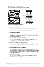
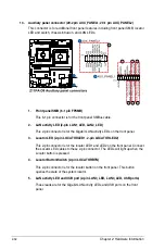
13. Auxiliary panel connector (20-2 pin AUX_PANEL1, 20-1 pin AUX_PANEL2)
This connector is for additional front panel features including front panel SMB, locator
LED and switch, chassis intrusion, and LAN LEDs.
1. Front panel SMB (6-1 pin FPSMB)
This 6-1 pin connector is for the front panel SMBus cable.
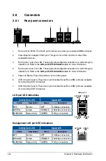
2. LAN activity LED (2-pin LAN1_LED, LAN2_LED)
This 2-pin connector is for the Gigabit LAN activity LEDs on the front panel.
3. Locator LED (2-pin LOCATORLED1, 2-pin LOCATORLED2)
This 2-pin connector is for the locator LED1 and LED2 on the front panel. Connect
the Locator LED cables to these 2-pin connector. The LEDs will light up when the
Locator button is pressed.
4. Locator Button/Switch (2-pin LOCATORBTN)
This 2-pin connector is for the locator button on the front panel. This button
queries the state of the system locator.
5. LAN activity LED and USB port (2-pin LAN3_LED, LAN4_LED, USB ports)
These leads are for the Gigabit LAN activity LEDs and USB ports on the front
panel.
Содержание Z11PA-D8 Series
Страница 1: ...Z11PA D8 Series User Guide ...
Страница 22: ...2 4 Chapter 2 Hardware Information 2 2 3 Motherboard layout ...
Страница 37: ...2 19 Z11PA D8 Series 10 PCH_MFG1 setting 3 pin PCH_MFG1 This jumper allows you to update the BIOS ME block ...
Страница 54: ...2 36 Chapter 2 Hardware Information ...
Страница 58: ...3 4 Chapter 3 Powering Up ...
Страница 106: ...4 48 Chapter 4 BIOS Setup ...
Страница 130: ...5 24 Chapter 5 RAID Configuration ...
Страница 148: ...6 18 Chapter 6 Driver Installation ...
Страница 150: ...A 2 Appendix Z11PA D8 Series block diagram with SATA M 2 device Z11PA D8 Series block diagram without SATA M 2 device ...
Страница 158: ...A 10 Appendix ...