


2-28
Chapter 2: Hardware Information
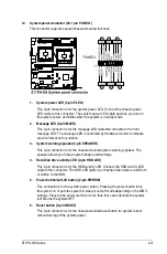
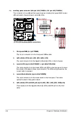
7.
CPU, front, and rear fan connectors (4-pin CPU_FAN1-2; FRNT_FAN1-4;
REAR_FAN1-2)
The fan connectors support cooling fans. Connect the fan cables to the fan connectors
on the motherboard, ensuring that the black wire of each cable matches the ground pin
of the connector.
•
DO NOT forget to connect the fan cables to the fan connectors. Insufficient air flow
inside the system may damage the motherboard components.
•
These are not jumpers! DO NOT place jumper caps on the fan connectors!
•
All fans feature the ASUS Smart Fan technology.
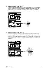
8.
Serial port connector (10-1 pin COM1)
This connector is for the serial COM port. Connect the serial port module cable to one
of these connectors, then install the module to a slot opening at the back of the system
chassis.
Содержание Z11PA-D8 Series
Страница 1: ...Z11PA D8 Series User Guide ...
Страница 22: ...2 4 Chapter 2 Hardware Information 2 2 3 Motherboard layout ...
Страница 37: ...2 19 Z11PA D8 Series 10 PCH_MFG1 setting 3 pin PCH_MFG1 This jumper allows you to update the BIOS ME block ...
Страница 54: ...2 36 Chapter 2 Hardware Information ...
Страница 58: ...3 4 Chapter 3 Powering Up ...
Страница 106: ...4 48 Chapter 4 BIOS Setup ...
Страница 130: ...5 24 Chapter 5 RAID Configuration ...
Страница 148: ...6 18 Chapter 6 Driver Installation ...
Страница 150: ...A 2 Appendix Z11PA D8 Series block diagram with SATA M 2 device Z11PA D8 Series block diagram without SATA M 2 device ...
Страница 158: ...A 10 Appendix ...