5-10
Chapter 5: RAID Configuration
3.
The utility immediately starts rebuilding after the disk is selected. When done, the
status of the degraded RAID volume is changed to
“Rebuild”
.
4.
Press <Esc> to exit Intel Rapid Storage Technology and reboot the system.
5.
Select
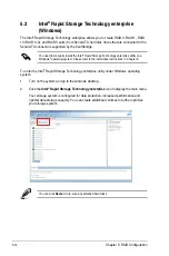
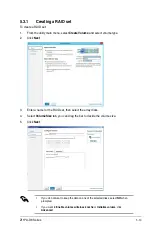
Start > Programs > Intel Rapid Storage > Intel Rapid Storage Console
or
click the
Intel Rapid Storage Technology
tray icon to load the Intel Rapid Storage
Manager utility.
6.
From the
View
menu, select
Advanced Mode
to display the details of the Intel Rapid
Storage Console.
7.
From the
Volumes view
option, select
RAID volume
to view the rebuilding status.
When finished, the status is changed to “
Normal
”.
Rebuilding the RAID with a new hard disk
If any of the SATA hard disk drives included in the RAID array failed, the system displays the
status of the RAID volume as “
Degraded
” during POST. You may replace the disk drive and
rebuild the RAID array.
To rebuild the RAID with a new hard disk:
1.
Remove the failed SATA hard disk and install a new SATA hard disk of the same
specification into the same SATA Port.
Select a destination disk with the same size as the original hard disk.
2.
Reboot the system then follow the steps in section
Rebuilding the RAID with other
non-RAID disk
.
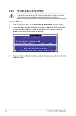
[ESC]-Exit
[ENTER]-Select Menu
[ ]-Select
Intel(R) Rapid Storage Technology enterprise - SATA Option ROM - 3.6.0.1023
Copyright(C) 2003-12 Intel Corporation. All Rights Reserved.
[
MAIN MENU
]
[
DISK/VOLUME INFORMATION
]
RAID Volumes: *=Data is Encrypted
ID Name Level1 Strip Size Status Bootable
1 Volume0 RAID1(Mirror) N/A 149.0GB
Rebuild
Yes
Physical Devices:
Port Drive Model Serial # Size Type/Status(Vol ID)
1 ST3160812AS 9LS0F4HL 149.0GB
Member Disk(0)
2 ST3160812AS 3LS0JYL8 149.0GB
Member Disk(0)
Volumes with “Rebuild” status will be rebuilt within the operating system.
3. Reset Disks to Non-RAID
4. Exit
1. Create RAID Volume
2. Delete RAID Volume
Содержание Z11PA-D8 Series
Страница 1: ...Z11PA D8 Series User Guide ...
Страница 22: ...2 4 Chapter 2 Hardware Information 2 2 3 Motherboard layout ...
Страница 37: ...2 19 Z11PA D8 Series 10 PCH_MFG1 setting 3 pin PCH_MFG1 This jumper allows you to update the BIOS ME block ...
Страница 54: ...2 36 Chapter 2 Hardware Information ...
Страница 58: ...3 4 Chapter 3 Powering Up ...
Страница 106: ...4 48 Chapter 4 BIOS Setup ...
Страница 130: ...5 24 Chapter 5 RAID Configuration ...
Страница 148: ...6 18 Chapter 6 Driver Installation ...
Страница 150: ...A 2 Appendix Z11PA D8 Series block diagram with SATA M 2 device Z11PA D8 Series block diagram without SATA M 2 device ...
Страница 158: ...A 10 Appendix ...

