

Chapter 1: Product Introduction
1-6
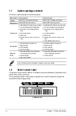
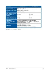
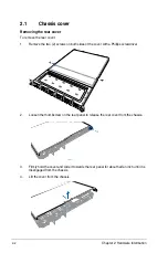
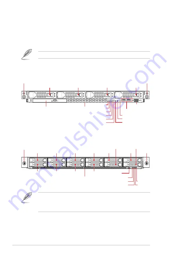
1.4
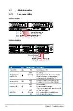
Front panel features
The barebone server displays a simple yet stylish front panel with easily accessible features.
The power and reset buttons, LED indicators, slim type optical drive (optional on RS700A-
E9-RS4 only), two USB ports (on RS700A-E9-RS4 only), and VGA port (on RS700A-E9-RS4
only) are located on the front panel.
Refer to section
1.7 LED information
for the LED descriptions.
•
Bay 1 to bay 4 supports hybrid SAS/SATA.
•
Bay 5 to bay 8 supports hybrid NVMe/SAS/SATA.
•
Bay 9 to bay 12 supports NVMe by default.
1
2
3
4
1
2
Optical drive (optional)
Asset tag
Asset tag
Rack screw
Rack screw
Rack screw
Rack screw
USB ports
VGA port
LAN 2 LED
Power LED
LAN 1 LED
Message LED
LAN 4 LED
LAN 3 LED
Message LED
Location LED
Power button
LAN 2 LED
Power button
Location button
LAN 1 LED
Reset button
Storage device LED
Bay 1
Bay 1
Bay 3
Bay 5
Bay 7
Bay 9
Bay 10
Bay 11
Bay 12
Bay 2
Bay 2
Bay 4
Bay 6
Bay 8
Bay 3
Bay 4
RS700A-E9-RS4
RS700A-E9-RS12
Содержание RS700A-E9-RS12
Страница 1: ...1U Rackmount Server User Guide RS700A E9 Series RS700A E9 RS4 RS700A E9 RS12 ...
Страница 70: ...Chapter 4 Motherboard Information 4 2 4 1 Motherboard layout ...
Страница 92: ...Chapter 4 Motherboard Information 4 24 ...
Страница 135: ...ASUS RS700A E9 Series 6 9 6 Click Finish to complete the installation 5 Click Install to start the installation process ...
Страница 136: ...6 10 Chapter 6 Driver Installation ...
Страница 137: ...Appendix Appendix This appendix includes additional information that you may refer to when configuring the motherboard ...
Страница 138: ...A 2 Appendix KNPP D32 block diagram ...
Страница 144: ...A 8 Appendix ...


