Operating Instructions for Ascoline 700, AGH 2xx, 4xx, 6xx
ascobloc
Gastro-Gerätebau GmbH
D-01156 Dresden, Grüner Weg 29
Germany
Tel. +49 351 4533-0
Fax: +49 351 4537-339
E-mail:
AGH2XX.doc, Status: 23.05.2013
Subject to change without notice!
14
9.2 Cooking zone burners
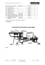
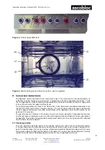
Refer to figure on conversion instructions for gas cooking zones.
The main nozzle (B) is located in front of the burner injector. Remove the grub screw at the side of the
injector and pull the nozzle holder with main nozzle out of the injector. Unscrew the main nozzle (A/F 14)
from the nozzle holder and screw in the new nozzle till the end stop is reached.
The small adjustment nozzle (A) is screwed in on each all-gas valve at the top left. Unscrew small
adjustment nozzle (black O-ring) with flat-blade screwdriver and replace with new nozzle.
9.3 Pilot flame burners in the cooking zones
The pilot flame nozzle is changed from above. Remove the pot grid support and pull off the pilot burner
cap (C). Loosen the plug screw at the top A/F 14 and unscrew the pilot burner nozzle using a long box
spanner A/F 5.5 (with clamping ring, whenever possible).
9.4 Oven burners
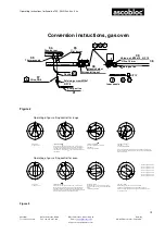
(See figure in conversion instructions for gas range with gas-fired oven)
The main nozzle (F) of the oven burner is behind the lower front panel. Once the lower front panel has
been removed, unscrew the lock nut (D) on the nozzle holder, undo screw (E) and remove old main
nozzle (F). Assemble screw (E), new nozzle (F) and spring, and insert. Carefully turn the screw till the
end stop is reached and screw on the lock nut.
Change the small adjustment nozzle (green O-ring) in the same way as for the cooking zone burner.
The pilot flame nozzle (G) lies underneath the pilot burner. Unscrew the pilot gas line (H) from the floor
and pull lightly downwards. Change the ignition nozzle (G), a small cap fixed to the end of the ignition gas
line, and screw on again.
Once the conversion is completed, the appliance must be subjected to a complete test just as if it were an
initial commissioning!


