Operating Instructions for Ascoline 700, AGH 2xx, 4xx, 6xx
ascobloc
Gastro-Gerätebau GmbH
D-01156 Dresden, Grüner Weg 29
Germany
Tel. +49 351 4533-0
Fax: +49 351 4537-339
E-mail:
AGH2XX.doc, Status: 23.05.2013
Subject to change without notice!
12
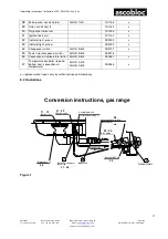
Düse
Überwurfschraube M10x1
Doppelkegelring RD4
Zündgasleitung
Luft- Regulierungsmutter
Hauptgasleitung
Überwurfmutter M16x1,5 SW 19
Doppelkegelring 10 mm
Zündbrenner
Backrohrbrenner
Thermoelement
Umstellanleitung Gas - Backrohr
SW 10
Düsenträger
H
G
D E F
D
E
F
Innendüse
SW 12
34
35
33
37
38
41
39
36
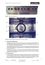
Figure 2
ZURÜCK nach rechts bis Rastpunkt Vollbrand 8 drehen,
Knebel leicht gedrückt nach rechts über Zündstellung
bis zur Aus- Stellung bringen
Betätigung Gas- Einstellglied Backrohr
8
7
6
5
4
3
2
1
8
7
6
5
4
3
2
1
8 7
6
5
4
3
2
1
Klappenöffnung anbrennen, ca. 10 Sekunden
stufenlos einstellbar
8
7
6
5
4
3
2 1
Stellung 1- ca.140°C
Stellung 2- ca.150°C
Stellung 3- ca.170°C
Stellung 4- ca.185°C
Stellung 5- ca.205°C
Stellung 6- ca.225°C
Stellung 7- ca.245°C
Stellung 8- ca.270°C
Aus- Stellung
Stellglied geschlossen
Zündstellung
Knebel tief drücken, ca. 30° nach links
in Zündstellung drehen, gedrückt halten und mit
Gasanzünder Zündbrennerflamme anbrennen, ca.
10 Sekunden gedrückt halten, danach ungedrückt auf
Vollbrand bis Anschlag nach links ca. 60° drehen
Vollbrandstellung
Knebel drücken, ca. 60° nach links
Kleinbrand stufenlos einstellbar
Kleinbrandstellung
Kleinbrand stufenlos einstellbar,
ZURÜCK nach rechts bis Rastpunkt Vollbrand drehen,
weiter zurück nach rechts bis Anschlag Zündstellung drehen,
Knebel leicht drücken und in Aus- Stellung bringen
Betätigung Gas- Einstellglied Herd
Aus- Stellung
Stellglied geschlossen
Zündstellung
Knebel drücken, ca. 30° nach links
in Zündstellung drehen, gedrückt halten und mit
Gasanzünder Zündbrennerflamme unterhalb der
gedrückt halten, danach leicht gedrückt auf
Vollbrand 8 nach links ca. 80° drehen
Vollbrandstellung 8
Knebel im Bereich von ca. 140° nach links
zwischen Stellung 8 bis 1 rasterartig
Kleinbrandstellung 1
Zwischenbereiche stufenlos einstellbar,
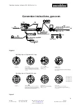
Figure 3
Conversion instructions, gas oven
Oven burner
Pilot burner
Nozzle holder
Inner nozzle
Main gas line
Olive, 10 mm
Union nut, M16x1.5 A/F 19
Thermocouple
Nozzle
Pilot gas line
Retaining screw M10x1
Air regulating nut
Olive, RD4
Operating of gas setting control for range
Off position
Actuator closed
Ignition position
Press in the knob deeply, turn approx. 30° to the left to the
ignition position, hold in the pressed-in position and light the
pilot flame with the gas igniter, keep pressed-in for 10 sec,
then release to the full flame
Turn to the left by about 60° to
the end stop
Full flame setting
Press knob, approx. 60° to the left
Low flame
Continuously adjustable
Low flame setting
Low flame
Continuously adjustable
Back to the right till the click-in position for full flame is reached, turn
further to right to the ignition position end stop, press knob lightly and
bring to off position
Operating of gas setting control for oven
Off position
Actuator closed
Ignition position
Press in the knob deeply, turn approx. 30° to the left to the
ignition position, hold in the pressed-in position and light the
pilot flame below the flap opening with the gas igniter, keep
pressed-in for 10 sec, then turn to the left by approx. 80°, while
keeping slightly depressed, to full flame position 8
Full flame position 8
Knob in the region of 140° to the left between
positions 8 and 1 can be continuously adjusted in
click-in
Continuously adjustable
Low flame setting 1
Intermediate ranges are continuously adjustable
Turn BACK to the right till it clicks in at full flame position 8,
depress knob slightly and turn to the right via the ignition position
to the OFF position
Position 1- approx. 140 °C
Position 2- approx. 150 °C
Position 3- approx. 170 °C
Position 4- approx. 185 °C
Position 5- approx. 205 °C
Position 6- approx. 225 °C
Position 7- approx. 245 °C
Position 8- approx. 270 °C
A/F 12
A/F 10


