Chapter 3 Installing the switch
43
Console cable pinouts
The Aruba X2C2 RJ45 to DB9 Console Cable (JL448A) has an RJ-45 plug on one end and a DB-9 female
connector on the other end.
Table 24
describes the mapping of the RJ-45 to DB-9 pins.
Figure 27:
RJ-45 to DB-9 pinouts
10. Connect the network cables
Connect the network cables, described under “Cabling Infrastructure” (
1. Prepare the installation site
), from the
network devices or your patch panels to the RJ-45 out-of-band management port on the switch or to any
transceivers you have installed in the switch.
Using the RJ-45 out-of-band management port
If you plan to manage the switch from a dedicated management network, connect an RJ-45 network cable from the
management network to the Mgmt port. The Mgmt port supports 10, 100, and 1000 Mbps connections.
To connect:
Push the RJ-45 plug into the RJ-45 port until the tab on the plug clicks into place. When power is on for the switch
and for the connected device, the Link LED for the port should light to confirm a powered-on device (for example,
an end node) is at the other end of the cable.
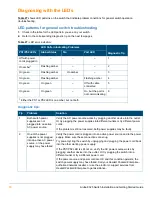
If the Link LED does
not
go on when the network cable is connected to the port, see
“Diagnosing with the LEDs”
on page 50
in the Troubleshooting chapter.
To disconnect:
Press the small tab on the plug and pull the plug out of the port.
Table 24:
Mapping of RJ-45 to DB-9
RJ-45 (Signal reference from Chassis)
DB-9 (Signal reference from PC)
Reserved
1
8
CTS
Reserved
2
6
DSR
TXD
3
2
RXD
Reserved
4
1
DCD
GND
5
5
GND
RXD
6
3
TXD
Reserved
7
4
DTR
Reserved
8
7
RTS
–
–
9
RI
12345678
5 4 3 2 1
9 8 7 6
Содержание 8325 Series
Страница 6: ...6 Aruba 8325 Switch Installation and Getting Started Guide...
Страница 48: ...48 Aruba 8325 Switch Installation and Getting Started Guide...
Страница 58: ...58 Aruba 8325 Switch Installation and Getting Started Guide...
Страница 62: ...62 Aruba 8325 Switch Installation and Getting Started Guide...

