


Chapter 2 Introducing the Aruba 8325 Switch
13
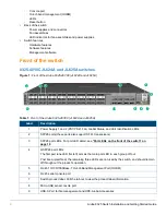
Management ports
Console port
The Aruba 8325-48Y8C and 8325-32C switches include an RJ-45 serial console port. This port is used to connect
a console to the switch by using an RJ-45 serial cable (not supplied). A DB9-to-RJ-45 console cable can be
ordered from HPE: JL448A, Aruba X2C2 RJ45 to DB9 Console Cable.
The 8325-48Y8C switches also include an additional Micro USB serial console port. This port can be used to
connect a console to the switch by using a standard Micro USB cable (not supplied). The Micro USB connector has
precedence for input. If both cables are plugged in, the console output is echoed to both the RJ-45 and the Micro-
USB ports, but the input is only accepted from the Micro-USB port.
For more information on the console connection, see
“9. Connect a management console” on page 41
. The
console can be a PC or workstation running a VT-100 terminal emulator, or a VT-100 terminal.
Out-of-band management (OOBM) port
This RJ-45 port is used to connect a dedicated management network to the switch. To use it, connect an RJ-45
network cable to the management port to manage the switch through SSH or Telnet from a remote PC or a UNIX
workstation.
To use this port, see the
Aruba 8325 Fundamentals Guide for ArubaOS-CX
. For more detailed information, refer to
the switch software manuals for your switch provided at
www.hpe.com/networking/ResourceFinder
.
A networked out-of-band connection through the management port allows you to manage data network switches
from a physically and logically separate management network.
USB-A port
A USB-A port for file management, downloading switch software code, or use of HPE-Aruba accessories. This port
uses a USB Type-A connector and complies with all USB protocols and standards.
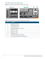
Chassis LEDs on the front of the switch
•
Table 8 on page 15
describes the switch chassis LEDs.
•
Table 10 on page 17
describes the switch port LEDs and their different behaviors for the JL624A and JL625A.
•
Table 12 on page 18
describes the switch port LEDs and their different behaviors for the JL626A an JL627A.
Figure 4:
Chassis LEDs for the Aruba 8325-48Y8C (JL624A and JL625A)
1
2
4
5
3
Содержание 8325 Series
Страница 6: ...6 Aruba 8325 Switch Installation and Getting Started Guide...
Страница 48: ...48 Aruba 8325 Switch Installation and Getting Started Guide...
Страница 58: ...58 Aruba 8325 Switch Installation and Getting Started Guide...
Страница 62: ...62 Aruba 8325 Switch Installation and Getting Started Guide...


