background image

Aruba 8325 Switch Series
Installation and Getting Started Guide

Part Number: 5200-5297
Published: January, 2019 
Edition: 1

Содержание 8325 Series

Страница 1: ...Aruba 8325 Switch Series Installation and Getting Started Guide Part Number 5200 5297 Published January 2019 Edition 1...

Страница 2: ...technical or editorial errors or omissions contained herein Confidential computer software Valid license from Hewlett Packard Enterprise required for possession use or copying Consistent with FAR 12 2...

Страница 3: ...ts not included 27 Installation procedures 28 Summary 28 Installation precautions 29 1 Prepare the installation site 30 2 Install power supplies 30 3 Install fan assemblies 31 4 Power on the switch an...

Страница 4: ...d network communications 53 Battery 54 Downloading new switch software 54 Hewlett Packard Enterprise Customer Support Services 54 Chapter 6 Specifications 55 Switch specifications 55 Physical 55 Elect...

Страница 5: ...rary at http www hpe com networking ResourceFinder The display and command line illustrated in this document are examples and might not exactly match your particular switch or environment The switch a...

Страница 6: ...6 Aruba 8325 Switch Installation and Getting Started Guide...

Страница 7: ...G SFP SFP28 8p 100G QSFP QSFP28 Back to Front 6 Fans and 2 PSU Bundle JL625A Includes a 48 port of 10 25Gbps and 8 port of 40 100Gbps switch with six fans and two power supplies installed with back to...

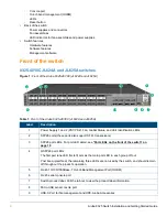
Страница 8: ...2 PS1 PS2 Fan Global Status and Unit Identification LEDs 2 SFP28 ports these ports also support SFP transceivers 3 SFP28 port LEDs For port LED detail see Port LEDs on the front of the switch on page...

Страница 9: ...l four interface groups are configured to 25 Gbps To configure the speed for an interface group to 10 Gbps use the following command system interface group 1 2 3 4 speed 10g 25g For example to configu...

Страница 10: ...left acts as the main port LED in each group of four Post boot up self test the remaining three LEDs are not used by the switch and should remain off throughout the product s operation 4 RJ 45 10 100...

Страница 11: ...ce groups must be configured to the user s intended installation The default speed for all interface groups is 25 Gbps Table 5 Optional network connectivity speeds and technologies Transceiver form fa...

Страница 12: ...the ArubaOS Switch and ArubaOS CX Transceiver Guide at http www hpe com networking ResourceFinder 2 10GBase T transceiver limited support only supported in ports 1 2 4 5 7 8 10 11 Use in any other po...

Страница 13: ...RJ 45 port is used to connect a dedicated management network to the switch To use it connect an RJ 45 network cable to the management port to manage the switch through SSH or Telnet from a remote PC...

Страница 14: ...ruba 8325 48Y8C JL624A and JL625A Label Description 1 Power Supply 1 PS1 LED 2 Power Supply 2 PS2 LED 3 Fan LED 4 Global Status LED 5 Unit Identification LED Table 7 Chassis LED labels for the Aruba 8...

Страница 15: ...assed self test and is powered up normally with all power supplies and fans installed and no faults are present Flashing amber The switch initialization is in progress during bootup A fault or initial...

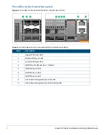
Страница 16: ...Table 9 Port LED labels for the Aruba 8325 48Y8C JL624A and JL625A Label Description 1 Upper SFP28 port LED 2 Middle SFP28 port LED 3 Lower SFP28 port LED 4 QSFP28 port LED and lane 1 indicator 5 QSF...

Страница 17: ...alid link at 100 40 Gbps Fast flashing1 of the Lane 1 LED indicates port activity at 100 Gbps Slow flashing2 of the Lane 1 LED indicates port activity at 40 Gbps Flashing amber When the Global Status...

Страница 18: ...ctivity LED Table 12 Port LED behavior for the Aruba 8325 32C JL626A and JL627A Chassis LEDs Function State Meaning QSFP28 port LEDs To display link and activity information for the port On flashing g...

Страница 19: ...information for the port On green Shows a valid link Off Port is disabled not connected or not receiving a link beat signal Management port Act LED To display activity information for the port Flashi...

Страница 20: ...A and JL625A Table 13 Aruba 8325 switch product label Label Description 1 Product label top side Information includes the serial number and MAC address 2 Product label bottom side Information includes...

Страница 21: ...d front to back air flow blue back to front air flow 13 Ground lug Table 15 Back of the Aruba 8325 32C JL626A and JL627A labels and descriptions Label Description 1 Power supply 2 1 2 Fan assembly 6 3...

Страница 22: ...ates a BF cooling air flow Figure 11 Aruba 8325 power supplies The Aruba 8325 switch is shipped with two hot swappable field replaceable AC power supplies Each power supply has a country specific powe...

Страница 23: ...tch unit Off AC power is not connected to the power supply or if AC power is connected the power supply is in protection mode due to a voltage current thermal or short circuit condition Never insert o...

Страница 24: ...one or more of the fan assemblies have failed the front panel Fan LED will be on amber and failed fan assembly LEDs will be on red If multiple fans have failed the switch should be immediately powere...

Страница 25: ...w hpe com networking ResourceFinder The Aruba 8325 switch is not compatible with fan assemblies from other Aruba hardware platforms Table 20 Fan assembly LED behavior Fan assembly LED Function State M...

Страница 26: ...r out of band switch management Web browser interface An easy to use built in graphical interface that can be accessed from common web browsers Support for the Spanning Tree Protocol to eliminate netw...

Страница 27: ...729 J9891A Israel 8121 1004 J9899A Australia New Zealand 8121 0837 J9883A Japan 8121 1143 J9893A Brazil 8121 1071 J9894A Switzerland 8121 0738 J9898A Chile 8121 0735 J9886A South Africa 8121 0737 J989...

Страница 28: ...e switch page 34 The switch can be mounted in a 19 inch telco rack or in an equipment cabinet 7 Optional Install transceivers page 37 The switch has slots for installing SFP SFP28 and QSFP QSFP28 tran...

Страница 29: ...AC outlet should be near the switch and be easily accessible in case the switch must be powered off Do not install the switch in an environment where the operating ambient temperature exceeds its spec...

Страница 30: ...e the cooling air flow direction in an 8325 switch you must replace the existing power supplies and fan assemblies with power supplies and fan assemblies having the opposite air flow direction All fan...

Страница 31: ...itch If the switch is connected to an AC power source the fan assembly should immediately start running 3 For the 32 port switch fan assembly engage the retaining screw and tighten it Be sure to not o...

Страница 32: ...e Figure 15 Connecting power to the switch Check LEDs for proper switch operation Figure 16 Chassis LEDs for the Aruba 8325 48Y8C JL624A and JL625A Table 21 Chassis LED labels for the Aruba 8325 48Y8C...

Страница 33: ...QSFP28 Port LEDs Off unless a network cable is connected and the port is receiving link beat Table 22 Chassis LED labels for the Aruba 8325 32C JL626A and JL627A Label Description 1 UID LED Locator o...

Страница 34: ...h with the included eight 8 mm M4 screws The brackets must only be attached for mid mounting the switch in a two post rack Ensure the holes in the bracket are aligned with the correct holes in the swi...

Страница 35: ...h in a two post rack Four post rack mount option The Aruba 8325 switch can be mounted in four post racks and cabinets by using the Aruba X474 4 Post Rack Kit JL483B sold separately The JL483B Aruba X4...

Страница 36: ...ve it vertically until rack holes line up with the front post bracket holes and then insert and tighten the four number 12 24 screws holding the brackets to the rack For safe operation please read the...

Страница 37: ...Lock the position of the rear post bracket ears using the included position locking screws Figure 22 Locking the position of rear post brackets 7 Install transceivers You can install or remove a trans...

Страница 38: ...the default speed duplex settings may be predefined for example to 1000 Mbps Full Duplex or otherwise set differently from the default configuration of your switch These setting differences may also...

Страница 39: ...X 10 02 or later at www hpe com networking ResourceFinder See also Interface Group operation on page 9 Installing transceivers Hold the transceiver by its sides and gently insert it into either of the...

Страница 40: ...the switch it will move outward slightly then pull it from the slot To remove the transceivers that have the wire bail lower the bail until it is approximately horizontal and then using the bail pull...

Страница 41: ...hods Out of band serial Use a serial cable not included for connecting a workstation running suitable VT 100 terminal emulation software directly to the switch s RJ 45 Console Port A DB9 to RJ 45 cons...

Страница 42: ...access To connect a console to the switch follow these steps 1 Connect the PC or terminal to the switch s Console Port using a console cable JL448A sold separately Figure 26 Connecting a console cabl...

Страница 43: ...network cable from the management network to the Mgmt port The Mgmt port supports 10 100 and 1000 Mbps connections To connect Push the RJ 45 plug into the RJ 45 port until the tab on the plug clicks...

Страница 44: ...n the type of transceivers installed See chapter 6 Cabling and technology information for cabling information For transceiver ports and in general for all the switch ports a network cable from an acti...

Страница 45: ...JL632A Front to Back cooling air flow Aruba 8325 650W 100 240VAC BF PSU JL633A Back to Front cooling air flow To remove a power supply 1 Remove the AC power cable from the failed power supply s conne...

Страница 46: ...8325 32C switches use different fan assemblies Each fan assembly type can only be installed in the correct switch model Two fan assemblies are available for use with the 8325 48Y8C Aruba 8325 48Y8C F...

Страница 47: ...the handle of the failed fan assembly pull it straight out to remove it from its slot 5 Insert the new fan assembly fully into the slot so that its face plate is flush with the back face of the switc...

Страница 48: ...48 Aruba 8325 Switch Installation and Getting Started Guide...

Страница 49: ...miswired cables may cause network collisions and other network problems and can seriously impair network performance Use a new correctly wired cable or compare your cable to the cable in chapter 6 Ca...

Страница 50: ...gged into an active AC power source Verify the AC power source works by plugging another device into the outlet Or try plugging the power supplies into different outlets or try different power cords I...

Страница 51: ...port Only ports 1 2 4 5 7 8 10 and 11 support 10GBase T transceivers The transceiver may have failed The switch port may have failed Check the switch Event Log and show interface command output for in...

Страница 52: ...tached device also MUST be configured as Full duplex If the configurations don t match the results could be a very unreliable connection or no link at all If the other procedures don t resolve the pro...

Страница 53: ...t are displayed Additionally you can check the switch event log which can be accessed from the console using the show events command Testing switch to device network communications You can perform the...

Страница 54: ...ck Products available at http www hpe com support Safety Compliance EnterpriseProducts ATTENTION ll y a danger d explosion s il y a remplacement incorrect de la batterie Remplacer uniquement avec une...

Страница 55: ...325 32C BF 6 F 2 PS Bdl JL627A 43 8 cm 17 26 in 51 5 cm 20 28 in 4 3 cm 1 73 in 9 5 kg 21 lb Product AC Voltage Maximum current Frequency range Aruba 8325 650W 100 240VAC FB PSU JL632A Aruba 8325 650W...

Страница 56: ...s JL624A JL625A JL626A and JL627A Operating Non Operating Temperature 0 C to 40 C 32 F to 104 F up to 3 0 km 10 000 ft 40 C to 70 C 40 F to 158 F up to 4 6 km 15 000 ft Relative humidity non condensin...

Страница 57: ...GBASE eSR not an IEEE standard EN IEC 60825 Class 1 Laser Product Laser Klasse 1 25GBASE LR IEEE 802 3cc 25GBASE LR EN IEC 60825 Class 1 Laser Product Laser Klasse 1 40GBASE SR4 IEEE 802 3ba 40GBASE S...

Страница 58: ...58 Aruba 8325 Switch Installation and Getting Started Guide...
Страница 59: ...5e or better is recommended See Note on 1000BASE T cable requirements on page 59 1 10 Gbps Operation Category 6 or 6A 100 ohm 4 pair UTP cable or Category 6A or 7 100 ohm 4 pair STP cable complying w...

Страница 60: ...NEXT which can arrive upon the cable due to cables placed in close proximity to the data cables It is recommended that cable dressing be done carefully and in compliance with recommendations in the TI...

Страница 61: ...BASE eSR4 multimode fiber 1500 MHz km 3500 MHz km 2 330 meters 2 550 meters 40GBASE LR4 single mode fiber N A 2 10 000 meters 40GBASE ER4 single mode fiber N A 2 40 000 meters3 40GBASE BiDi multimode...

Страница 62: ...62 Aruba 8325 Switch Installation and Getting Started Guide...
Страница 63: ...des up to date customer care support and warranty information at http www hpe com networking support Additionally your Hewlett Packard Enterprise authorized network reseller can provide you with assis...

Страница 64: ...tworking Software www hpe com networking software Hewlett Packard Enterprise Networking website www hpe com info networking Hewlett Packard Enterprise My Networking website www hpe com networking supp...

Страница 65: ...ister your device for remote support For more information and device support details go to the following website www hpe com info insightremotesupport docs Documentation feedback Hewlett Packard Enter...

Отзывы: