


OPERATING AND MAINTENANCE MANUAL FU 321M
22
COOLING SYSTEM
The cooling system consists of a coolant tank, a motor pump and a spout. The
tank is situated in the base of the machine.
The quantity of the cooling liquid is about 50 l.
The base of the machine is provided with a tray whose purpose is to collect the
coolant from the slides and the knee.
Coolant prolongs the life span of the cutting edges and improves the finish of the
machine surfaces. Not only should these factors to taken into account on choosing
a coolant type, but the damage it can do to the paintwork of the machine and
rust it can cause to exposed metal surfaces as well. The motor pump situated at
the back part of the column is started by a switch "Coolant ON/OFF" / Pos.44,
Fig.3a / on the control panel.
The coolant driven by the motor pump is pumped to the spout at the front part
of the column. The spout can be adjusted to any position and remains in this
position with required angle.
The spout has a cylindrical part with a double function - shut-off cock and setting
of the coolant flow by means of turning the tap. Even if the motor pump is ON
there is no problem in having the tap closed
Recommended Coolants
Mobil - Mobilcut 262
If coolants are used from another firms it is recommended COSHH sheets.
Warning:
When working with materials that may be flamable such as Alumium etc.
use high flash point coolant.
Содержание FU 321M
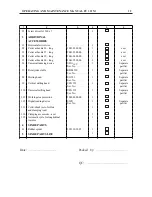
Страница 32: ...OPERATING AND MAINTENANCE MANUAL FU 321M 29 ELECTRIC EQUIPMENT DETAILS...
Страница 33: ...OPERATING AND MAINTENANCE MANUAL FU 321M 30 ELECTRIC ARRANGEMENT...
Страница 34: ...OPERATING AND MAINTENANCE MANUAL FU 321M 31 BUTTON ARRANGEMENT FRONT PANEL 10...
Страница 35: ...OPERATING AND MAINTENANCE MANUAL FU 321M 32 BUTTON ARRANGEMENT SIDE PANEL WARNING...
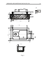
Страница 36: ...OPERATING AND MAINTENANCE MANUAL FU 321M 33 Fig 1 DRAWINGS AND CHARTS A A 7 8 10 1 2 3 4 5 A A 6 9...
Страница 39: ...OPERATING AND MAINTENANCE MANUAL FU 321M 36 Fig 3a 45 41 46 51 48 43 52 44 42 53 49 50 47...
Страница 40: ...OPERATING AND MAINTENANCE MANUAL FU 321M 37 SEMI AUTOMATIC CYCLE...
Страница 42: ...OPERATING AND MAINTENANCE MANUAL FU 321M 39 Fig 5 320 4 x 18 0 43 12 1 2 3 18 0 027 30 30 63 63 90...
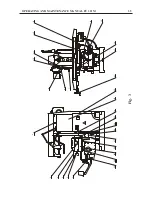
Страница 43: ...OPERATING AND MAINTENANCE MANUAL FU 321M 40 Fig 6 1 2...
Страница 46: ...OPERATING AND MAINTENANCE MANUAL FU 321M 43 Fig 10 4 3 2 1...
Страница 52: ...OPERATING AND MAINTENANCE MANUAL FU 321M 49 Fig 16 3 ELECTRIC CIRCUIT DIAGRAM...
Страница 57: ...OPERATING AND MAINTENANCE MANUAL FU 321M 54 Fig 18 3 4 1 2 1 1 1 1 1 1 7 5 6 1 1...
Страница 60: ...OPERATING AND MAINTENANCE MANUAL FU 321M 57 Fig 21 OPERATOR S WORKING POSITION ON THE MACHINE...
Страница 62: ...OPERATING AND MAINTENANCE MANUAL FU 321M 59 Fig 23 MARKING ON THE PACKING 2170 2370...
Страница 63: ...OPERATING AND MAINTENANCE MANUAL FU 321M 60 Fig 24 DIGITAL READOUT SYSTEM...