


OPERATING AND MAINTENANCE MANUAL FU 321M
21
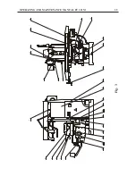
LUBRICATION
The lubrication circuit diagram is shown on Fig.8 and Fig.8a indicate the recom-
mended lubricants for the various units.
The spindle gear box is lubricated by a
reversible
pump. The proper lubrication
of the pump is checked through the oil level indicator 4. The oil is poured in the
spindle gear box through plug 3 and is drained through pipe 1.
The feed gear box and the knee mechanisms are lubricated by a gear pump with
motor 17. The oil in the knee is poured after removing cover 10 and is drained
by loosening plug 14.
The lubrication of the guide ways for movement along the axes and the mecha-
nisms placed in the saddle is performed by the centralized System for lubrication.The
set lubrication time is for universal operation and is set by the manufacturer before
the delivery of the machine. For special operations the time for lubrication is
necessary to be changed (see "Operating and Maintenance Manual of System for
lubrification").
Pour the oil after removal of the cup 8 and the level of the poured oil can be
inspected on the transparent tank 9.
The oil for the vertical screw is supplied after removing cap 11. For this purpose
the knee should be lifted to upper end position. The oil should be to the middle
of the oil level indicator 16. It is drained through plug 15 as the knee should be
in lower end position. The tank cleaning and the complete oil change is performed
during machine repair.
When the vertical screw is in operation, it is necessary to move the knee once
or twice per workshift in both end positions.
The bearing in the yoke brackets is lubricated by a wick - feed lubricator. The
oil is poured through plug 5. The oil level should not be more than the middle
of the oil level indicator 6.
During operation follow the instructions on the machine panels.
Содержание FU 321M
Страница 32: ...OPERATING AND MAINTENANCE MANUAL FU 321M 29 ELECTRIC EQUIPMENT DETAILS...
Страница 33: ...OPERATING AND MAINTENANCE MANUAL FU 321M 30 ELECTRIC ARRANGEMENT...
Страница 34: ...OPERATING AND MAINTENANCE MANUAL FU 321M 31 BUTTON ARRANGEMENT FRONT PANEL 10...
Страница 35: ...OPERATING AND MAINTENANCE MANUAL FU 321M 32 BUTTON ARRANGEMENT SIDE PANEL WARNING...
Страница 36: ...OPERATING AND MAINTENANCE MANUAL FU 321M 33 Fig 1 DRAWINGS AND CHARTS A A 7 8 10 1 2 3 4 5 A A 6 9...
Страница 39: ...OPERATING AND MAINTENANCE MANUAL FU 321M 36 Fig 3a 45 41 46 51 48 43 52 44 42 53 49 50 47...
Страница 40: ...OPERATING AND MAINTENANCE MANUAL FU 321M 37 SEMI AUTOMATIC CYCLE...
Страница 42: ...OPERATING AND MAINTENANCE MANUAL FU 321M 39 Fig 5 320 4 x 18 0 43 12 1 2 3 18 0 027 30 30 63 63 90...
Страница 43: ...OPERATING AND MAINTENANCE MANUAL FU 321M 40 Fig 6 1 2...
Страница 46: ...OPERATING AND MAINTENANCE MANUAL FU 321M 43 Fig 10 4 3 2 1...
Страница 52: ...OPERATING AND MAINTENANCE MANUAL FU 321M 49 Fig 16 3 ELECTRIC CIRCUIT DIAGRAM...
Страница 57: ...OPERATING AND MAINTENANCE MANUAL FU 321M 54 Fig 18 3 4 1 2 1 1 1 1 1 1 7 5 6 1 1...
Страница 60: ...OPERATING AND MAINTENANCE MANUAL FU 321M 57 Fig 21 OPERATOR S WORKING POSITION ON THE MACHINE...
Страница 62: ...OPERATING AND MAINTENANCE MANUAL FU 321M 59 Fig 23 MARKING ON THE PACKING 2170 2370...
Страница 63: ...OPERATING AND MAINTENANCE MANUAL FU 321M 60 Fig 24 DIGITAL READOUT SYSTEM...