


OPERATING AND MAINTENANCE MANUAL FU 321M
19
DESCRIPTION OF THE MAIN MACHINE UNITS
The disposition of machine main units is shown in Fig.25.
BODY, YOKE AND BRACKETS
The Body of the machine is a basic part where all units and mechanisms are
assembled upon. The Body is fixed on a cast iron base which is used as a coolant
tank as well.
The Spindle gear box electric motor is mounted in the back recess of the Body
and the electric cabinet is fitted in the right recess of the machine Body.
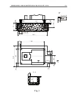
The Yoke slides along the horizontal guideways. It is fixed on the Body by nuts
10 / Fig.3 /. The tightening force exerted on the spanner should be about
500-600 N. One or two brackets (depending on the type of work done) in which
the bearings of the cutter arbors are positioned, are placed in the yoke front end.
The bracket holes are machined on spot individually for each machine, so the
brackets cannot be used on other milling machines. They are tightened to the Yoke
by means of nuts 11 / Fig.3 /.
The radial backlash of bearing 7 / Fig.1, A-A / is adjusted by nut 8. The good
functioning of the bearings 7 depends on the proper backlash adjustment and the
sufficient lubrication. Non-observance of any of these conditions will cause seizure
or premature wear out and breakage of the bearing 7.
SPINDLE GEAR BOX
The gear box is mounted in the machine body and is driven by an electric motor
through V-belts. The gear box ensures 18 spindle speeds / Fig.12 /.
The radial backlash of the spindle bearing is adjusted by the manufacturer and is
within 0.004-0.005 mm. In case the bearing should be replaced by a new one, the
radial backlash is adjusted with the help of nut 2 and ring 1 / Fig.4 /.
Belts 4 / Fig.10 / are tensioned as follows: open cover 22 / Fig.3 /, unscrew the
nuts 3 / Fig.10 / and by bolts 2 / Fig.10 / the rocker 1 / Fig.10 / is inclined till
tensioning of belts is performed. Then the bolts 2 are locked by nuts 3.
Belt tensioning is checked as it is pressed in the middle with force 100 to 150 N.
The feed should be 20-25 mm.
CAUTION:
Maximum allowed spindle torque should be 600 Nm.
Содержание FU 321M
Страница 32: ...OPERATING AND MAINTENANCE MANUAL FU 321M 29 ELECTRIC EQUIPMENT DETAILS...
Страница 33: ...OPERATING AND MAINTENANCE MANUAL FU 321M 30 ELECTRIC ARRANGEMENT...
Страница 34: ...OPERATING AND MAINTENANCE MANUAL FU 321M 31 BUTTON ARRANGEMENT FRONT PANEL 10...
Страница 35: ...OPERATING AND MAINTENANCE MANUAL FU 321M 32 BUTTON ARRANGEMENT SIDE PANEL WARNING...
Страница 36: ...OPERATING AND MAINTENANCE MANUAL FU 321M 33 Fig 1 DRAWINGS AND CHARTS A A 7 8 10 1 2 3 4 5 A A 6 9...
Страница 39: ...OPERATING AND MAINTENANCE MANUAL FU 321M 36 Fig 3a 45 41 46 51 48 43 52 44 42 53 49 50 47...
Страница 40: ...OPERATING AND MAINTENANCE MANUAL FU 321M 37 SEMI AUTOMATIC CYCLE...
Страница 42: ...OPERATING AND MAINTENANCE MANUAL FU 321M 39 Fig 5 320 4 x 18 0 43 12 1 2 3 18 0 027 30 30 63 63 90...
Страница 43: ...OPERATING AND MAINTENANCE MANUAL FU 321M 40 Fig 6 1 2...
Страница 46: ...OPERATING AND MAINTENANCE MANUAL FU 321M 43 Fig 10 4 3 2 1...
Страница 52: ...OPERATING AND MAINTENANCE MANUAL FU 321M 49 Fig 16 3 ELECTRIC CIRCUIT DIAGRAM...
Страница 57: ...OPERATING AND MAINTENANCE MANUAL FU 321M 54 Fig 18 3 4 1 2 1 1 1 1 1 1 7 5 6 1 1...
Страница 60: ...OPERATING AND MAINTENANCE MANUAL FU 321M 57 Fig 21 OPERATOR S WORKING POSITION ON THE MACHINE...
Страница 62: ...OPERATING AND MAINTENANCE MANUAL FU 321M 59 Fig 23 MARKING ON THE PACKING 2170 2370...
Страница 63: ...OPERATING AND MAINTENANCE MANUAL FU 321M 60 Fig 24 DIGITAL READOUT SYSTEM...