


OPERATING AND MAINTENANCE MANUAL FU 321M
20
SPINDLE GEAR BOX CHANGER
It is a separate unit mounted on the left side of the body. It is shown in Fig.9.
FEED GEAR BOX
It is mounted on the knee left side. The feed gear box is driven by an electric
motor through a rubber spider.
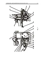
KNEE
All mechanisms realizing the machine feed motions are fitted to the knee
/ Fig.14 /.
The safety clutch (shaft VIII - Fig.14) disengages the feed motion in case of
overloading. It is adjusted to transfer a torque of 140 Nm. In order to adjust the
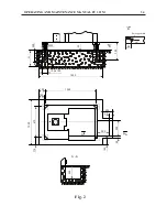
safety clutch by the nut 1 / Fig.6 / first you have to remove the cover 30
/ Fig.3 / and then take the split pin 2 / Fig.6 / out.
The manual cross feed is switched off by cams 28 / Fig.3 / and microswitches
29 / Fig.3 / and the vertical - by cams 24 / Fig.3 / and microswitches 27
/ Fig.3 /.
When the vertical travel is not used, the knee should be tightened to the body with
the handles 26 / Fig.3 /.
SLIDE, SADDLE AND WORKING TABLE
The slide is moving along the knee. It can be locked to the knee by means of
handles 14 / Fig.3 /.
The saddle can swivel at 45 in both directions. It is locked by screws 2 and 25
/ Fig.3 /.
A semi-automatic device for longitudinal screw backlash compensation is built -
in the saddle. This backlash compensation is required only at climb milling and
is done by handle 16 / Fig.3 /.
The working table is clamped to the saddle by the screws 12 / Fig.3 /.
Содержание FU 321M
Страница 32: ...OPERATING AND MAINTENANCE MANUAL FU 321M 29 ELECTRIC EQUIPMENT DETAILS...
Страница 33: ...OPERATING AND MAINTENANCE MANUAL FU 321M 30 ELECTRIC ARRANGEMENT...
Страница 34: ...OPERATING AND MAINTENANCE MANUAL FU 321M 31 BUTTON ARRANGEMENT FRONT PANEL 10...
Страница 35: ...OPERATING AND MAINTENANCE MANUAL FU 321M 32 BUTTON ARRANGEMENT SIDE PANEL WARNING...
Страница 36: ...OPERATING AND MAINTENANCE MANUAL FU 321M 33 Fig 1 DRAWINGS AND CHARTS A A 7 8 10 1 2 3 4 5 A A 6 9...
Страница 39: ...OPERATING AND MAINTENANCE MANUAL FU 321M 36 Fig 3a 45 41 46 51 48 43 52 44 42 53 49 50 47...
Страница 40: ...OPERATING AND MAINTENANCE MANUAL FU 321M 37 SEMI AUTOMATIC CYCLE...
Страница 42: ...OPERATING AND MAINTENANCE MANUAL FU 321M 39 Fig 5 320 4 x 18 0 43 12 1 2 3 18 0 027 30 30 63 63 90...
Страница 43: ...OPERATING AND MAINTENANCE MANUAL FU 321M 40 Fig 6 1 2...
Страница 46: ...OPERATING AND MAINTENANCE MANUAL FU 321M 43 Fig 10 4 3 2 1...
Страница 52: ...OPERATING AND MAINTENANCE MANUAL FU 321M 49 Fig 16 3 ELECTRIC CIRCUIT DIAGRAM...
Страница 57: ...OPERATING AND MAINTENANCE MANUAL FU 321M 54 Fig 18 3 4 1 2 1 1 1 1 1 1 7 5 6 1 1...
Страница 60: ...OPERATING AND MAINTENANCE MANUAL FU 321M 57 Fig 21 OPERATOR S WORKING POSITION ON THE MACHINE...
Страница 62: ...OPERATING AND MAINTENANCE MANUAL FU 321M 59 Fig 23 MARKING ON THE PACKING 2170 2370...
Страница 63: ...OPERATING AND MAINTENANCE MANUAL FU 321M 60 Fig 24 DIGITAL READOUT SYSTEM...