4 / 54
P/N 466-
2915 (ML) • REV C • ISS 11DEC20
Area and Status LEDs are flashing and the LCD display reads
System Fault:
•
Verify the D+ and D− wire connections (may be reversed
or open circuit).
•
Verify the address DIP switches of the RAS is set to the
proper address.
•
Verify that the control panel or four-door DGP is polling the
RAS address.
ATS1115-N and ATS1116-N RAS with Smart Card reader
does not respond to a Smart Card:
•
The RAS may actually be an ATS1110-N or ATS1111-
N type that is not fitted with a Smart Card reader.
•
The Smart Card may not be programmed (blank).
RX and TX LED Indications
RX and TX LEDs are provided on the circuit board to assist in
fault diagnosis, and are visible when the rear plastic cover is
removed.
•
Rx: The yellow Rx LED flashes to indicate polling data is
being received on the system bus from the panel. If the
LED does not flash, the control panel is not operational or
the bus is faulty (usually cabling).
•
Tx: The red Tx LED flashes to indicate the RAS is replying
to polling from the control panel. If the Rx LED flashes but
the Tx LED does not, the RAS is not programmed to be
polled in the control panel or is addressed incorrectly.
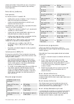
Programming map
CARRIER F&S, RAS1115.V10
0-EXIT, Menu:
1-Access LED options
0-EXIT, Menu:
➔
LED enabled
*-Change, #-Exit
2-Night Light Options
0-Exit, Menu:
➔
Night Light On
*-Change, #-Exit
3-Keypad Backlight Options
0-Exit, Menu:
➔
Keypad Backlight On
*-Change, #-Exit
4-RTE (Egress) Control
0-Exit, Menu:
➔
RTE Only
*-Change, #-Exit
5-Reserved
0-Exit, Menu:
6-Factory Defaults
0-Exit, Menu:
➔
Set Factory Defaults?
*-Yes, #-No
7-Security Mode
0-Exit, Menu:
➔
Un-Secured Mode
*-Change, #-Exit
8-Valid Card Flash
0-Exit, Menu:
➔
Flash Enabled
*-Change, #-Exit
9-Protocol Options
0-Exit, Menu:
➔
Wiegand
*-Change, #-Exit
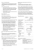
10-Card Beep Options
0-Exit, Menu:
➔
Card Beep Enabled
*-Change, #-Exit
11-Option Card
0-Exit, Menu:
➔
Option Card Enabled
*-Change, #-Exit
12-Last Card
0-Exit, Menu:
➔
FC=1, ID=1
#-Exit
Programming options
The ATS1110-N, ATS1111-N, ATS1115-N, and ATS1116-
N provide for a menu through which a number of options can
be set.
To enter the programming menu for the ATS111x-
N keypads:
1. Enter menu 28 of the control panel installer menu.
2. Press 2, Enter followed by the RAS address selected and
Enter to enter the RAS menu. The display now shows
“Carrier F&S, RAS111x-N” (x is 0, 1, 5 or 6, depending on
the type of keypad) followed by the version number.
3. Press Enter to proceed to the menu or press the menu
number followed by Enter to go to a menu item directly.
Menu 1, Access LED options
Controls the blue access LED (enabled by default). The blue
access LED may be disabled if not required.
Menu 2, Night light options
A dimly lit keypad backlight provides the night-light to easily
locate the keypad in dark locations (enabled by default).
Menu 3, Keypad backlight options
The keypad backlight turns on bright for night time illumination
of the key labels (enabled by default). If the keypad backlight is
not required, it may be disabled.
Menu 4, RTE (egress) control
The RAS is fitted with a request to exit (RTE) control port
(labelled IN) on the wiring connector. The OUT (open collector
terminal) may be used to control a door relay.
There are three options to choose from:
•
RTE Only: This option requires a simple push button to be
connected to the IN terminal. A press of the button will
release the door lock relay. Used for a quick exit from an
Area (enabled by default).
•
RTE Arm/Disarm: Do not use.
•
RTE Disabled: When the
“IN” terminal is not used, it is
recommended that it be disabled.
Menu 5, Reserved
Reserved for future use.
Menu 6, Factory Defaults
This option returns all RAS settings to the factory default
condition.
Содержание ATS111-N Series
Страница 54: ...54 54 P N 466 2915 ML REV C ISS 11DEC20 ...


