11
Linearis N+
5.2
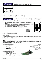
Set up limit switches (Self-adjusting switch cam)
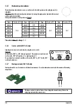
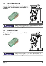
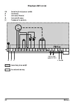
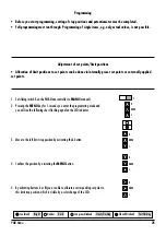
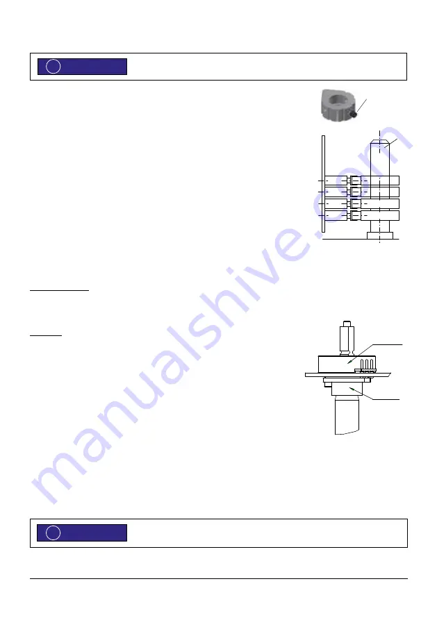
The switch cams are turnable by hand and can be fastened by a thread pin, e.g. if strong
vibrations apply.
1. Apply voltage (see page 10): Actuator rotates in given direction.
2. Switch off voltage when the desired end position has reached (no blocking of gear).
3. Turn switch cam L in rotating direction of the cam shaft E until limit path switch SL clicks.
Now the thread pin F can be fixed with a hex wrench (enclosed).
4. Set up switch cam R for contrary rotating direction as described under step 1–3.
5. Check setup by moving the actuator again electrically and adjust if necessary.
5.3
Optional modules and extra features
5.3.1
Potentiometer
Electrical connection
Connect terminals 18, 19 and 20 according to the desired requirements (voltage ≤ 50V); (see page 10). Use only separate
(shielded) wires.
Adjustment
Set up limit switch before adjusting the potentiometer P. Approach both end positions electrically
(see chapter 5.2).
Observe travel and potentiometer solution.
Do not overrun the ordered travel to avoid damage to the friction clutch R by permanent
override. Potentiometer P adjusts roughly automatically.
The travel of the valve is transferred to the rotating angle of the potentiometer by the friction
clutch R. Approach both end positions again electrically (see page 15) and adjust potentiometer
P with the friction clutch R.
5.3.2
Potentiometer with approval acc. to DIN EN 12067-2 (TÜV-Poti)
Fail-safe potentiometer return for regulation of fuel, air and exhaust streams in combination with electronic compound control
systems.
At delivery the wiper is in the electrical center.
ADVICE
!
1
2
R
E
S1
S2
SR
L
SL
P
R
F
ADVICE
!
Содержание Linearis N+
Страница 19: ...Manual for ARIS Microprocessor Controller PMR Nano PMRN1429EN01 Stellantriebe ...
Страница 31: ......


