10
Linearis N+
8
6 7
S1
11
9 10
5455
+
–
Strom-
ausgang
S2
Standard
Optionen
14
1213
S3
17
1516
S4
4.5.2
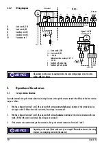
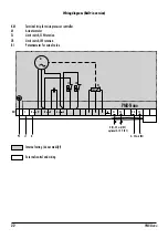
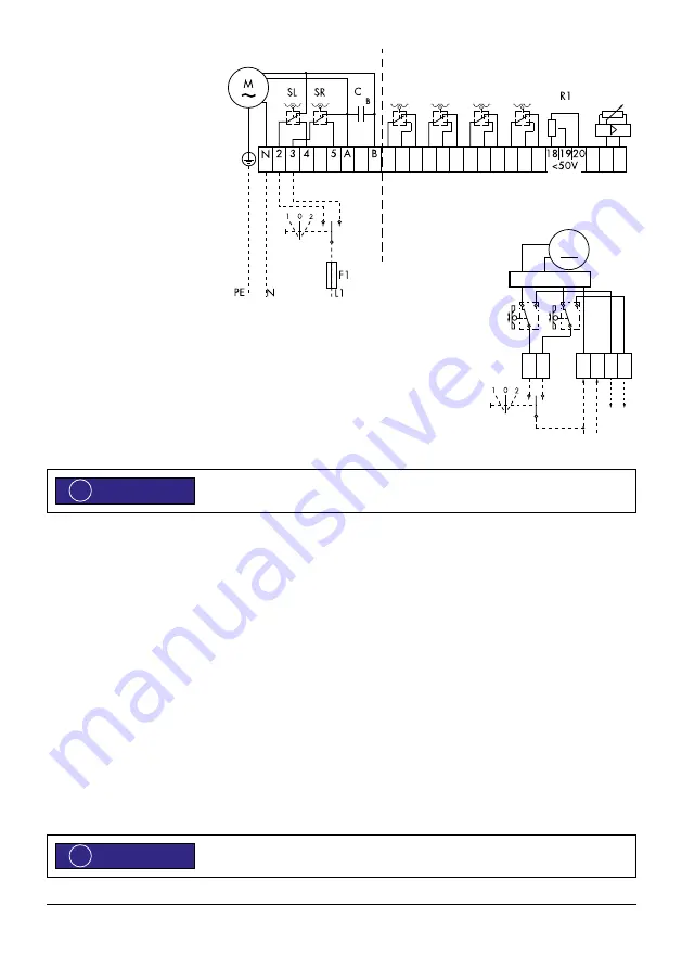
Wiring diagram
SL
Limit switch, CCW
SR
Limit switch, CW
S1
Auxiliary switch 1
S2
Auxiliary switch 2
R1
Potentiometer 1
All auxiliary switches must be operated within the same voltage range. Do not mix line
voltage with low voltage.
5.
Operation of the actuators
5.1
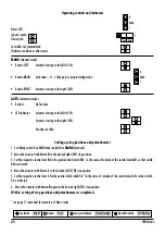
Set up rotation direction
Due to the internal wiring, the rotation direction (viewing direction is through the actuator towards the shaft) and the limit switches
assign as follows:
1. With line voltage on terminal 1 and 2, the actuator shaft rotates
counter-clockwise
. Limitation of this rotation direction
with upper switch SL. When the switch is activated, line voltage is on terminal 4.
2. With line voltage on terminal 1 and 3, the actuator shaft rotates
clockwise
. Limitation of this rotation direction with lower
switch SR. When the switch is activated, line voltage is on terminal 5.
3. If the actuator runs counterrotating to the commands, change the external connection of terminal 2 and 3 .
Depending on the model, limit switches may be arranged different than drawn in the wiring
diagram (see wiring diagram inside the actuator).
ADVICE
!
ADVICE
!
Current
output
Options
M
+L +R
5
T+
4
SL
SR
–
Steuerelektronik
+24V -24V
SL SR
24V DC
Option 24 V DC
see chapter 5.3.10
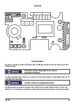
+L
Limit switch, CCW
+R
Limit switch, CW
T+ +24V DC
(Manual override see chapt. 5.3.9.1)
– -24V DC
4 Feedback left end position
5 Feedback right end position
Содержание Linearis N+
Страница 19: ...Manual for ARIS Microprocessor Controller PMR Nano PMRN1429EN01 Stellantriebe ...
Страница 31: ......


