15
Component settings
General layout:
On the main screen (Picture 5) touch the component which you would like to configure. Most
component screens have a similar structure: the left-side menu, Current value and Output
active/inactive icon, the performance Chart in the middle of screen and Settings values on the
right-hand.
The following icons are situated on the left-side menu: SYSTEM, CALIBRATION, SAVE,
RETURN.
SYSTEM icon is for System Configuration.
CALIBRATION icon allows the option of: QUICK and PRECISE calibration. Choose between
QUICK calibration using a known pre-measured value and PRECISE calibration using
calibration solutions. Follow the instructions on the screen to complete the calibration. It is
recommended to perform PRECISE calibrations on commissioning, every month and when a
new probe is installed.
Press the SAVE icon for saving new settings after editing. A pop-up screen with confirmation of
savings of new settings will appear. New settings will also be saved when pressing RETURN icon
and returning to the MAIN screen.
The performance Chart has historical values on the current date; week or month (Double click on
chart area to load the desired component). Also shown on the graph are indications of dosing
duty values for those periods.
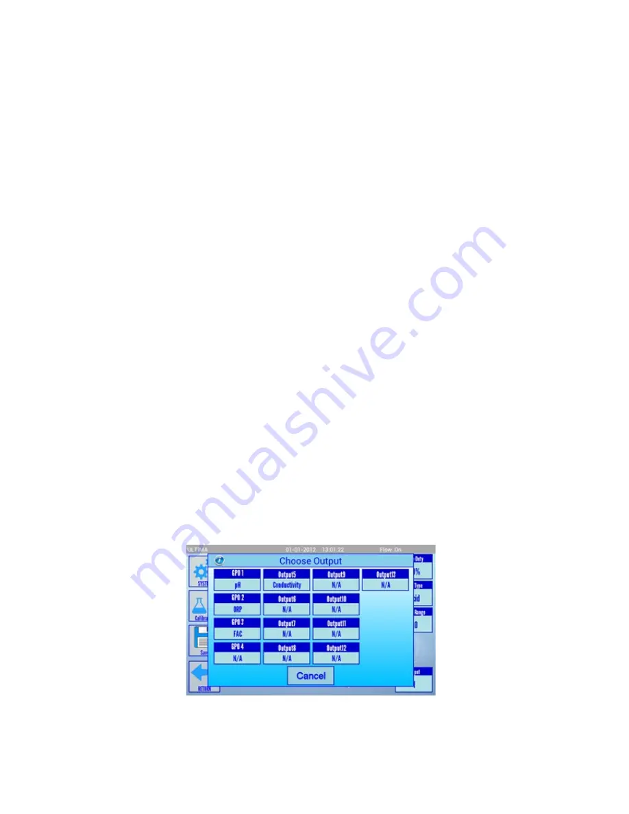
OUTPUT: This allows you to CHOOSE OUTPUT screen (PICTURE 10). Press the chosen output
to use that output instead of the currently assigned one if required.
CAUTION:
Use outputs 1 to 4 only as they are wired to the GPO plugs 1 to 4 labelled on the
protection cover inside the controller (Refer to the Picture 1. Protection cover) Outputs 5-8 should
be used only if they are wired according to the purchase order. Outputs 9 to 13 are low power
(can switch up to 50V/0.5A/10W peak) signal relays for use with switching dosing pumps or
similar applications.
Picture 10. Choose Output Screen
Содержание ULTIMA
Страница 1: ...1 Instruction Manual v 1 1 Cooling Tower Controllers ...
Страница 27: ...27 ATTACHMENT Typical Installation Diagrams ...
Страница 28: ...28 ...


