8
Quality for Professionals
6.2
Coupling
Lock the tractor lower link against lateral movement so
that it does not start swinging while driving.
Connect the GP 600 M1 to the tractor lower links, they
are standardised according to CAT 3N. This means that
the balls have a lateral distance of 965 mm. The width
of the ball is 45 mm.
Connect the brake system (optional).
Remove the wheel chocks (optional) and hang them
in the intended holder.
Release the parking brake (optional).
CAUTION:
Pay attention to the sequence for the connection! First couple the yellow
brake line, then the red.
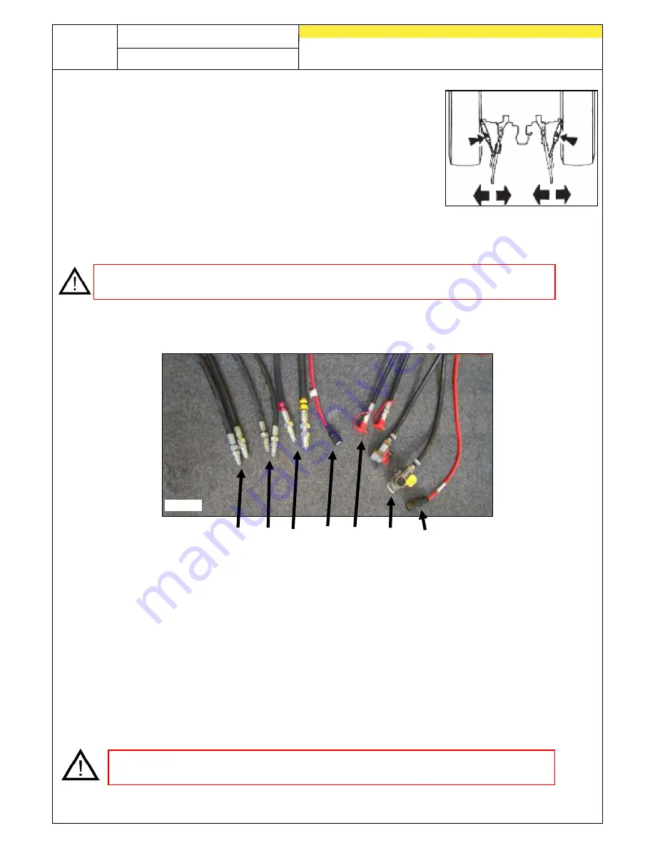
Connect the hydraulic hoses, lighting (optional) and electric cables (check the
function of the lights).
1. Hydraulic connections for the roller (yellow)
2. Hydraulic connections for the running gear (black)
3. Hydraulic connections for the PS implement plus pressureless return (optional)
4. Implement cable for the PS implement (optional)
5. Hydraulic connections for the folding mechanism (red)
6. Connections for the pneumatic brakes (optional)
7. Lighting for the GP 600 M1 (optional)
CAUTION:
Only connect the hydraulic hoses when the hydraulic system on the
towing vehicle and the GP 600 M1 are unpressurised.
Fig.: 7
Fig.: 8
1 2 3 4 5 6 7


