2–25
PacketMax 5000 Installation and Operation Manual, 10007678 Rev J
Chapter 2. Base Station Components
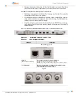
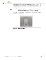
The BSR interfaces to the IF card of the WSS via a RG-6 cable. The input to the BSR
is a composite signal and comprises DC power, 20 MHz reference signal, 70 MHz
(IF) modulated signal, and the telemetry signals. The telemetry signals are used for
communication between BSR and WSS for controlling the RF parameters and also
for reporting radio status.
NOTE: A 1 m cable would have a loss of 0.5 dB. For more details on cable losses,
please refer to the Maximum Allowable Cable Loss for IF Cable section.
See Chapter 3,”Installing Radios and Antennas” for information and details on
installing the Base Station Radio.
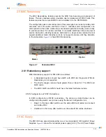
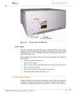
Figure 2-18
Base Station Radio
Содержание PacketMAX 5000
Страница 10: ...Preface Preface vi PacketMax 5000 Installation and Operation Manual 10007678 Rev J ...
Страница 14: ...Table Of Content TOC 4 PacketMax 5000 Installation and Operation Manual 10007678 Rev J ...
Страница 38: ...1 20 PacketMax 5000 Installation and Operation Manual 10007678 Rev J Chapter 1 Overview Of Base Station ...
Страница 64: ...2 26 PacketMax 5000 Installation and Operation Manual 10007678 Rev J Chapter 2 Base Station Components ...
Страница 104: ...5 16 PacketMax 5000 Installation and Operation Manual 10007678 Rev J Chapter 5 Commissioning the Base Station ...
Страница 114: ...A 10 PacketMax 5000 Installation and Operation Manual 10007678 Rev J Chapter A Event Reporting ...
Страница 124: ...C 6 PacketMax 5000 Installation and Operation Manual 10007678 Rev J Chapter C Cables Spares and Accessories ...
Страница 146: ...E 4 PacketMax 5000 Installation and Operation Manual 10007678 Rev J Chapter E Certifications ...
Страница 150: ...F 4 PacketMax 5000 Installation and Operation Manual 10007678 Rev J Chapter F Troubleshooting ...

