4–10
PacketMax 5000 Installation and Operation Manual, 10007678 Rev J
Chapter 4. Installing the Base Station ODU Radio and Antenna
The IF cable between the BS and BSR carries a multiplexed signal along with the DC
voltage.
They are identified below and the user should pay particular attention to the
choice of IF cable,
in field deployments as the cable loss is a function of length, fre-
quency and quality.
Following are the various signals the IF cable carries between BS and BSR.
DC voltage.
20 MHz reference signal.
70 MHz IF signal (bi-directional).
Telemetry link (260 and 420 MHz) for communication between BS-BSR and
BSR-BS (bi-directional).
When choosing IF cable of any given length and quality, the user should look at the
maximum allowable loss of the cable that is recommended below for reliable opera-
tion of the system. The below table allows sufficient margin for surge protectors and
connectors.
is based on a nominal Base Station Radio operating voltage of
52 Volts DC and 75% duty cycle.
Apart from the above recommended cable loss characteristics, the RF shielding capa-
bility of the cable should be least 90 dB or better. As a last note, choice of quality
connectors and cables with good weatherability and outdoor rated is highly recom-
mended for reliable performance of the system.
Typical cable lengths for LMR Cables from Times Microwave, Inc
Following are the assumptions in coming up with the prescribed lengths.
Two surge protectors are used each with ~ 0.1 dB loss at 70 MHz.
Connectors on either end have a loss of ~ 0.1 dB each.
PM 3000 BS outputs a nominal voltages of 52V at the IF port.
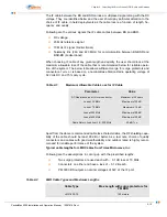
Table 4-1
Maximum Allowable Cable Loss for IF Cable
Parameter
Value
DC Resistance inner +Outer conductor.
Maximum of 22 ohms
Loss at 20 MHz
Maximum of 20 dB
Loss at 70 MHz
Maximum of 9 dB
Loss at 260 MHz
Maximum of 20 dB
Loss at 420 MHz
Maximum of 20 dB
Cable Return Loss from 20 – 500 MHz
20 dB Typ
Table 4-2
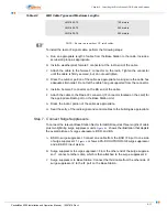
LMR Cable Types and Maximum Lengths
Cable Type
Max Length with surge protectors for
PM BSR
LMR-200-75
100 meters
Содержание PacketMAX 5000
Страница 10: ...Preface Preface vi PacketMax 5000 Installation and Operation Manual 10007678 Rev J ...
Страница 14: ...Table Of Content TOC 4 PacketMax 5000 Installation and Operation Manual 10007678 Rev J ...
Страница 38: ...1 20 PacketMax 5000 Installation and Operation Manual 10007678 Rev J Chapter 1 Overview Of Base Station ...
Страница 64: ...2 26 PacketMax 5000 Installation and Operation Manual 10007678 Rev J Chapter 2 Base Station Components ...
Страница 104: ...5 16 PacketMax 5000 Installation and Operation Manual 10007678 Rev J Chapter 5 Commissioning the Base Station ...
Страница 114: ...A 10 PacketMax 5000 Installation and Operation Manual 10007678 Rev J Chapter A Event Reporting ...
Страница 124: ...C 6 PacketMax 5000 Installation and Operation Manual 10007678 Rev J Chapter C Cables Spares and Accessories ...
Страница 146: ...E 4 PacketMax 5000 Installation and Operation Manual 10007678 Rev J Chapter E Certifications ...
Страница 150: ...F 4 PacketMax 5000 Installation and Operation Manual 10007678 Rev J Chapter F Troubleshooting ...

