4–5
PacketMax 5000 Installation and Operation Manual, 10007678 Rev J
Chapter 4. Installing the Base Station ODU Radio and Antenna
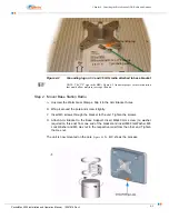
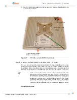
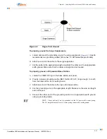
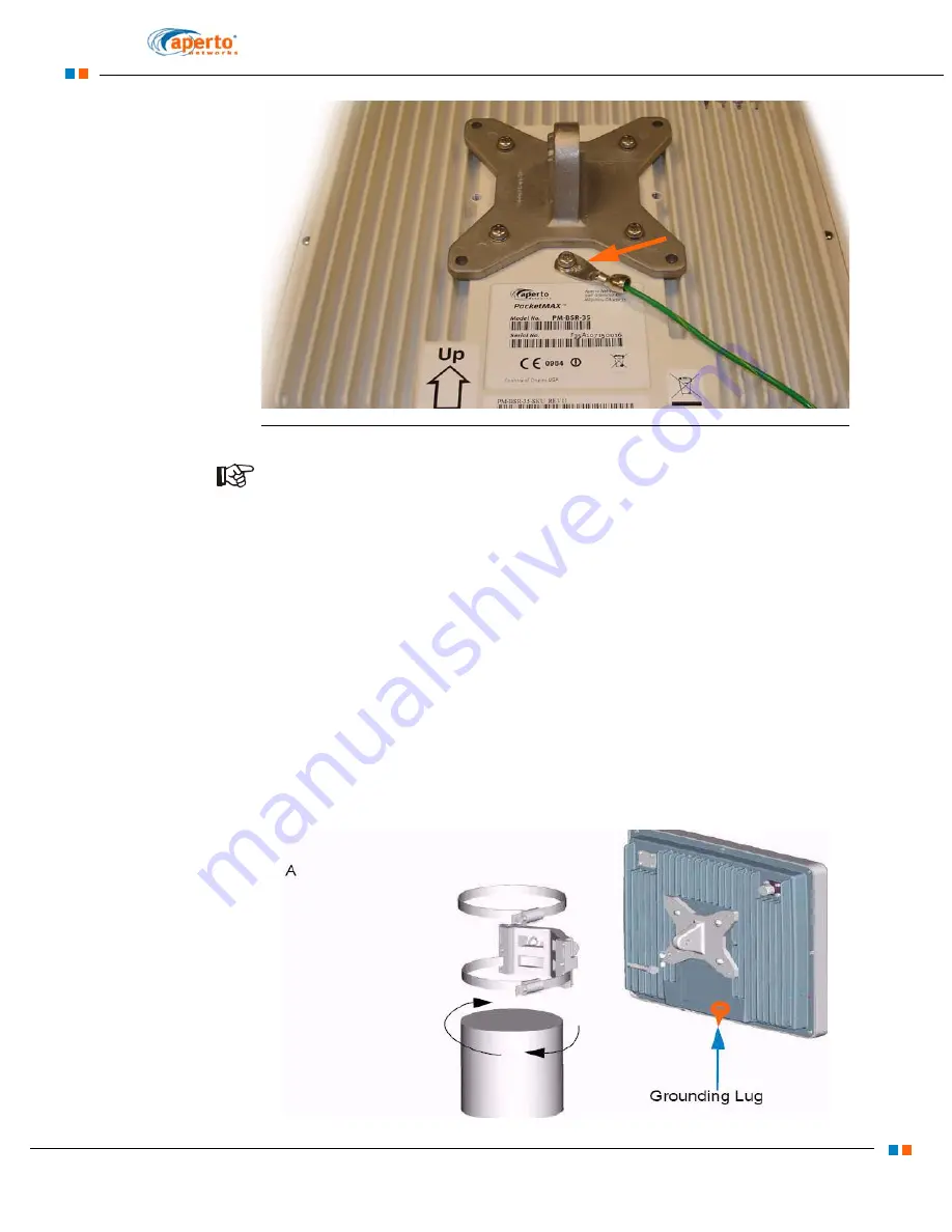
Figure 4-2
Grounding lug on 3.3 and 3.5 GHz radio attached to base bracket
NOTE: The “UP” sign in the BSR ( Figure 4-2 ) indicates proper vertical orientation
that would allow moisture to escape the unit.
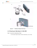
Step 2. Mount Base Station Radio
A.
Unscrew the Warm Gear Clamps. Slip it in the Arm Bracket holes.
B.
Wrap it around the pole and screw it tightly.
C.
Insert M5 screws through the bracket to the unit. Tighten the screws.
D.
Attach Arm Bracket to the Base Support. Insert M8x40 mm screw (no washer
required on this end) from one end of the bracket and insert M8 Flat Washer, M8
Lock Washer and M8 Hex nut in the respective order from the other end. Tighten
the Hex nut.
The unit is now mounted on the pole.
A, B,C shows the process.
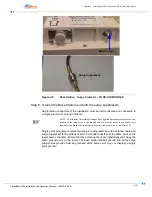
Grounding lug
12 or 10 Gauge
grounding wire
Содержание PacketMAX 5000
Страница 10: ...Preface Preface vi PacketMax 5000 Installation and Operation Manual 10007678 Rev J ...
Страница 14: ...Table Of Content TOC 4 PacketMax 5000 Installation and Operation Manual 10007678 Rev J ...
Страница 38: ...1 20 PacketMax 5000 Installation and Operation Manual 10007678 Rev J Chapter 1 Overview Of Base Station ...
Страница 64: ...2 26 PacketMax 5000 Installation and Operation Manual 10007678 Rev J Chapter 2 Base Station Components ...
Страница 104: ...5 16 PacketMax 5000 Installation and Operation Manual 10007678 Rev J Chapter 5 Commissioning the Base Station ...
Страница 114: ...A 10 PacketMax 5000 Installation and Operation Manual 10007678 Rev J Chapter A Event Reporting ...
Страница 124: ...C 6 PacketMax 5000 Installation and Operation Manual 10007678 Rev J Chapter C Cables Spares and Accessories ...
Страница 146: ...E 4 PacketMax 5000 Installation and Operation Manual 10007678 Rev J Chapter E Certifications ...
Страница 150: ...F 4 PacketMax 5000 Installation and Operation Manual 10007678 Rev J Chapter F Troubleshooting ...

