background image

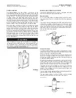
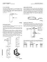
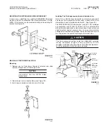
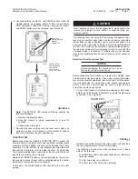
RELEASE CIRCUIT TEST MODULE

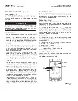
The release circuit test module, Part No. 423541, is used in place of
the gas motor during test procedures to simulate squib actuation or
gas motor actuation on CHECKFIRE MP-N systems (indicator lamp
on). It is also used when verifying time delay durations. See Figure
13.

FIGURE 13

003015

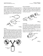
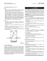
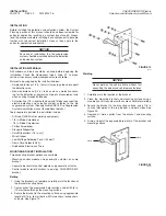
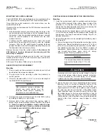
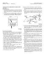
SPLICING DEVICE

The In-Line Splice Kit, Part No. 428375, is required for detection
wire connection between the control module and the linear detec-
tion wire or between separate pieces of linear detection cable.
When the splicing device is used in the system, it is recommended
to fill the splice body, Part No. 426783, with a high grade of sili-
cone sealant (Dow Corning 737 or equal) to make a proper seal.
The kit consists of the necessary number of components to
assemble 10 complete assemblies. See Figure 14.

FIGURE 14

007045

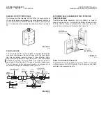
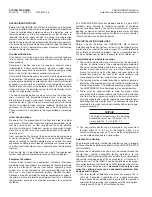
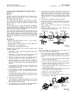
EXTENDER CABLE ASSEMBLY/BATTERY EXTENDER
CABLE ASSEMBLY

The Extender Cable Assembly, Part No. 426601, is used to
conduct functional tests. It, along with the Battery Extender Cable,
Part No. 428042, allows separation of the cover from the enclo-
sure while maintaining circuit integrity. See Figure 15.

FIGURE 15

002978

RS232 PC INTERFACE CABLE KIT

The RS232 PC Interface Cable Kit, Part No. 423524, is required
to field program the MP-N module. The kit contains the cable
assembly and programming disc.

SYSTEM COMPONENTS

PAGE 6

REV. 02        2012-MAY-18

CHECKFIRE MP-N Electric

Detection and Actuation System Manual

EXTENDER
TEST CABLE,
PART NO. 426601

EXTENDER
BATTERY CABLE,
PART NO. 428042

LINEAR
DETECTION
WIRE

STRAIN RELIEF,
PART NO. 423546

SPLICE
BLOCK,
PART NO.
433284

OVERLAP
CONDUCTORS
UNDER SCREW
TERMINALS

LINEAR
DETECTION
WIRE

LINEAR
DETECTION
WIRE

LINEAR
DETECTION
WIRE

STRAIN RELIEF,
PART NO. 423546

SPLICE BODY,
PART NO. 426783

3/4 IN.

(2 cm)

3/8 IN.

(1 cm)

Содержание Checkfire MP-N

Страница 1: ...002750 CHECKFIRE MP N ELECTRIC DETECTION ACTUATION SYSTEM Installation Recharge Inspection and Maintenance Manual ...

Страница 2: ...rformed monthly or sooner depending on operating and or environmental conditions Maintenance shall be performed semi annually or sooner depending on operating and or environmental conditions The application and use of the CHECKFIRE MP N system is limited to the application and uses described in this manual For other applications contact your local authorized ANSUL distribu tor or the ANSUL technic...

Страница 3: ... 2012 MAY 18 Complete manual has 02 been reformatted and renumbered as Page 1 was deleted All pages have been changed to Rev 02 regardless of previous revision number Revision indicators 䊳 mark current technical revisions only DATE PAGE REV NO DATE PAGE REV NO Indicates revised information ...

Страница 4: ......

Страница 5: ...0 Pre installation Guidelines 10 11 INSTALLATION 12 24 Installation Materials 12 Mounting Bracket Installation 12 Mounting to Existing CHECKFIRE MP Bracket 13 Manual Actuator Installation 13 Mounting the Control Module 14 Gas Motor Actuator Assembly 14 Control Module Wiring Detection Wire Routing 14 18 Thermal Detector Installation 16 17 Pneumatic Linear Detector Installation 18 Initiating Input P...

Страница 6: ...ardous situation in which a person could experience minor or moderate personal injury if the situation is not avoided Addresses practices not related to personal injury such as a system part malfunctioning property damage or system failure NOTICE Addresses general practices or observations related to system function that are not related to personal injury 䊱 DANGER WARNING CAUTION CAUTION EXPLANATI...

Страница 7: ...or use only with ANSUL fire suppression systems requiring pneumatic input as a means of actuation The CHECKFIRE MP N system is typically used with an ANSUL A 101 Vehicle Fire Suppression system for 24 hour protection of equipment The system is particularly suited for the protection of mining equipment that is subjected to extreme environmental and physical conditions Some of its features include l...

Страница 8: ...iating input circuit to cause a release output or as a pressure switch feedback input circuit which will sound alarms and transfer the shutdown relay but will not cause a release output If selected as an initiating circuit to cause a release its operation will override the first time delay function and initiate a second time delay condition causing the shutdown relay to immediately operate and sys...

Страница 9: ... The MSHA CHECKFIRE MP N system is equipped with both manual and automatic agent release devices Manual Actuator A 1 4 in NPT street elbow is supplied with the actuator for conve nient connection of the 1 4 in actuation line to the fire suppression system The manual actuator is designed with a RED palm button which is attached to a cartridge seal piercing pin and a ring pin to guard against accide...

Страница 10: ...AR DETECTION WIRE The linear detection wire consists of two spring steel conductors which are separated by a heat sensitive insulator At the tempera ture rating of the wire 356 F 180 C the insulator melts allow ing the two conductors to make contact This contact provides electrical continuity between the two conductors The linear detec tion wire is supplied in lengths of 100 ft 30 5 m Part No 7123...

Страница 11: ...Battery Installation for proper battery replacement procedures See Figure 10 FIGURE 10 004877 END OF LINE RESISTOR The End Of Line Resistor Assembly Part No 426520 is required for supervision of the external input circuits The end of line resis tor assembly is available in a package of 10 Part No 426461 Each package consists of 10 of the required components to assemble 10 of the resistor assemblie...

Страница 12: ...mplete assemblies See Figure 14 FIGURE 14 007045 EXTENDER CABLE ASSEMBLY BATTERY EXTENDER CABLE ASSEMBLY The Extender Cable Assembly Part No 426601 is used to conduct functional tests It along with the Battery Extender Cable Part No 428042 allows separation of the cover from the enclo sure while maintaining circuit integrity See Figure 15 FIGURE 15 002978 RS232 PC INTERFACE CABLE KIT The RS232 PC ...

Страница 13: ...ule and pneu matic actuator Cable must be round jacketed with an O D of 0 13 to 0 25 in suitable for the intended usage Terminals 9 10 11 12 and 13 Not Used Terminals 14 15 16 Shut Down Relay Cable must be round jacketed with an O D of 0 13 in to 0 25 in suitable for the intended usage 3 amp maximum load Relay specification 4A 250VAC 3A 30VDC resistive Normally open normally closed set of contacts...

Страница 14: ...ssed and the LED will pulse at a rate of 4 pulses per second while the second time delay runs through its timing cycle After the time delay setting is reached it will pulse another 30 seconds at the same rate After that the control module will go into the post discharge mode at which time the Alarm LED and Release LED will pulse at a rate of one pulse per 10 seconds PRESSURE SWITCH CIRCUIT FEED BA...

Страница 15: ...d energy and should be handled with care Do not compact for disposal Before disposal each battery must be fully discharged and electrically isolated by enclosing in a plastic bag and sealing the bag Do not dispose of in fire Check applicable solid waste disposal regulations for proper disposal of more than one battery BATTERY REPLACEMENT While in use the battery requires replacement every year or ...

Страница 16: ...tion system is the primary means of protecting equipment from fire an effective fire protection package also includes provisions for equipment shutdown The CHECKFIRE MP N control module contains 3 amp 30VDC shutdown relay contacts to facilitate connection of shutdown devices recommended by the vehicle manufacturer Example opening or closing of coolant over temperature alarm will bring about proper...

Страница 17: ...e placement of thermal spot detectors should be based on the following requirements 1 They can be wired directly to the control module using approved cable Cable must have a temperature rating of 392 F 200 C minimum 16 18 gauge two conductor with drain minimum O D of 0 230 in 5 8 mm Again placement of the detectors should allow for incoming and outgoing wire connections 2 Secure the detector with ...

Страница 18: ...de Screwdriver 1 4 in Blade Screwdriver Phillips Screwdriver Standard Sidecutters Small Sidecutters 1 4 in cut Wire Stripper Low Wattage Soldering Pencil 35 watt Rosin Core Solder 60 40 Rubberized Electricianʼs Tape MOUNTING BRACKET INSTALLATION Three mounting bracket options are available Mounting control module and pneumatic actuator on same bracket Separate brackets for control module and pneum...

Страница 19: ... at the intersection of each actuation device branch See Figure 23 The CHECKFIRE MP N System output using LT 10 R cartridge can pressurize up to 75 lineal ft 22 8 m of 1 4 in actuation line with up to eight agent tanks and or accessories Check valves are used to protect against pressure loss if one or more actuator cartridges are removed or damaged and by isolating each branch line they reduce the...

Страница 20: ...to the actuator body and properly secured with the allen head set screw FIGURE 24 003925 CONTROL MODULE WIRING DETECTION WIRE ROUTING Mounting 1 Using the system layout sketch investigate each point where the wire will be secured to the vehicle Keep in mind all the guidelines in the System Planning Section Do this on a vehicle that has been operated recently to avoid securing the wire too close to...

Страница 21: ...8 Tighten screws on splice block 9 Once splice block assembly is completed on both sets of wire ends apply Dow Corning 737 sealant or equal to strain relief threads going into the splice body 10 Securely tighten the strain relief into the splice body Note Do not tighten compression nut unto wire at this time 11 Slide splice body assembly near splice block Fill splice body approximately 3 4 full wi...

Страница 22: ...t head screws supplied in detector clamp package See Figure 28 FIGURE 28 000875 3 Starting at the ANSUL CHECKFIRE Control Module measure and route the cable to the first detector Note If protective tubing is to be used make certain cable is run through it between each detector 4 The circuit cable is 3 conductor It consists of two insulated wires and one bare ground wire Cut all wires equal in leng...

Страница 23: ... to a rigid support Run the detection circuit cable to the box and attach to grounding screw See Figure 30 15 Attach the end of line resistor assembly Part No 426520 See Figure 30 See instruction sheet included with end of line resistor shipping assembly for detailed assembly information 16 Run cable to the terminal strip at the control module Make certain cable is not subject to damage Install ca...

Страница 24: ...es a positive feed back that a discharge has occurred It also initiates shutdown functions and control module alarms regardless of the type of actuation either automatic or manual Initiating input circuit pressure switch input circuit must be wired to Terminals 5 and 6 on the control module terminal strip The pres sure switch circuit must also have an end of line resistor assem bly Part No 426461 ...

Страница 25: ...used The relay contact ratings are 3 amp 30 VDC resistive Only MSHA approved intrinsically safe circuitry may be connected to shutdown contacts 2 Terminals 14 NO 15 C and 16 NC are the shutdown relay terminals on the control module The ends of stranded wire should be tinned with 60 40 rosin core solder using a low wattage soldering pencil before connection to the control terminals Note Use 0 13 to...

Страница 26: ... remove the 3 6 VDC lithium battery requiring replacement see Figure 34a Check applicable solid waste disposal regulations for proper disposal of lithium batteries Do not discard battery in fire or general waste disposal FIGURE 34a 2 The MP N power circuitry may hold a residual charge even after battery removal Allow the module to remain unpowered for at least 30 seconds to ensure all residual cha...

Страница 27: ...e simulated fire condition or when actuated using an electric pull station The accuracy of the time delay setting s will also be verified during this test If the system is connected to a vehicle shutdown device the vehicle should be left running during this test to verify that the shutdown device is functioning If noted results are not attained refer to the Troubleshooting Section of this manual f...

Страница 28: ...n using a digital Ohmmeter measure the resistance between terminals 3 and 4 with the detec tion wire connected The resistance value should read approxi mately 4 7K ohms This will verify the circuit is intact and the end of the line resistor is connected Immediate Release Option 1 Using the jumper wire hold the wire on Terminals 5 and 6 This is the pull station circuit If the circuit was programmed...

Страница 29: ... button on manual actuator several times to ensure smooth movement 5 Install LT 10 R cartridge into manual actuator by completing the following steps Figure 36 a Make certain puncture pin is fully retracted and insert ring pin through actuator body into puncture pin shaft Attach visual inspection seal Part No 197 b Remove shipping cap and weigh cartridge before installa tion Replace if weight is 1...

Страница 30: ... to remove the required number square c Peel the protective backing from the number square to expose the adhesive d Place the number square on the space provided in the third sentence of Label No 79060 THIS VEHICLE WILL AUTOMATICALLY SHUTDOWN AFTER_____SECONDS FIGURE 39 000886 9 If a vehicle shutdown device is NOT installed affix the WHEN FIRE ALARM SOUNDS nameplate Part No 71086 near the operator...

Страница 31: ...ze an explosion proof pressure switch for shutdown If the pressure switch is connected to the system all responsible personnel should understand shutdown device operation and the length of the time delay in seconds If the delay reset button on the control module cover is pushed and released before the end of the pre alarm time delay period the time delay will auto matically repeat itself This dela...

Страница 32: ...screw NOTICE When gas motor is installed onto actuator body bottom of puncture pin must be flush with bottom of body 1 16 in 1 6 mm g Reattach thread connector to gas motor thread Hand tighten FIGURE 42 003945 7 Disconnect detection wire or thermal detector leads from the control module as follows a Loosen screws at terminals 3 and 4 of detection output module b Loosen strain reliefs on detection ...

Страница 33: ...K ohms This will verify the circuit is intact and the end of line resistor is connected 8 Check first time delay Alarm to Shutdown Using a short length of insulated wire stripped at both ends hold one end of the wire to Terminal 3 and the other end to Terminal 4 on the control module See Figure 43 FIGURE 43 002770 Using a jumper wire temporarily short Terminals 3 and 4 removing the jumper before t...

Страница 34: ...19 Record date of new battery installation on label located near battery Reinstall control module cover and depress RESET button Contact your local waste management company for informa tion concerning the correct disposal of lithium batteries 13 Reinstall LT 10 R cartridge Part No 423423 by completing the following steps a Make certain puncture pin is fully retracted and insert ring pin through ac...

Страница 35: ...0 00 00 00 however previous history will remain until deleted manually Below is a listing and explanation of each type of recorded history event All Clear The module is free of any fault or alarm conditions Amp Hours Limit Exceeded Indicates that the charge drawn off the battery has exceeded the recommended limit The battery must be serviced immediately Ver 4 11 only Amp Hours Reset Charge accumul...

Страница 36: ...al normal transferred off detection fault once every once every once every 10 seconds 10 seconds 10 seconds battery fault off pulsing off off pulsing pulsing normal normal transferred off release fault once every once every once every 10 seconds 10 seconds 10 seconds battery fault off pulsing off pulsing pulsing pulsing normal normal transferred off detection fault once every once every once every...

Страница 37: ...s pulsing off pulsing off pulsing pulsing transferred transferred transferred fired after release once every once every once every once every 3 seconds 10 seconds 10 seconds 10 seconds initiating circuit pulsing off off pulsing off pulsing normal normal transferred off No 2 once every once every once every battery normal 3 seconds 10 seconds 10 seconds initiating circuit No 2 pulsing off off pulsi...

Страница 38: ...h If switch No 1 is on the operation of the control module will correspond to the settings of the other manual programming switches If this switch is OFF Disable the operation of the control module will correspond to the settings of the PC program Switch No 2 This switch is used to select initiating circuit No 2 to operate as either an initiating input circuit or a pressure switch feedback ON Pres...

Страница 39: ...Software Version The GUI header shows which version of software is currently running This should read Ansul SetupSC V4 11 when used with the MP N control module 2 Firmware Version The Connected to box displays the current firmware revision level of the module connected to the PC 3 DipSwitch When this section displays Manual Programming OFF the module will respond to a connected PC If the DipSwitch...

Страница 40: ... PC to PC FIGURE 49 009036 8 Password The Password button opens the Enter Password window with options for entering or changing the password to protect access to the PC programming see Figure 50 FIGURE 50 009037 When changing the password for the module perform the following steps a If needed enter the factory default password CHKFRSCN Note Password is case sensitive b Click the Change Password bu...

Страница 41: ...rocedure Note If programming with the front cover assembly removed from the back box it is normal for the sounder and LEDʼs to pulse once every 10 seconds This will stop when the programming is completed and the computer and internal battery are discon nected Step No 3 Attach the RS 232 interface cable and associated USB to RS232 adapter if required between the computer and the CHECKFIRE MP N cont...

Страница 42: ...est MP N or SC N and the middle position is OFF 3 Steps for operation are a With slide switch select type of release circuit to be tested This will also turn the unit on b Press the reset button on the tester This will illuminate the READY LED if it is not already illuminated c Connect to control unit actuator cable d Proceed with activating output Refer to Function Test Page 21 in the Installatio...

Страница 43: ...Tubing 100 ft 30 5 m 4 1 81 416221 Spot Detector Bracket 1 0 45 416784 Amp Crimp Tool Spot Detector 1 0 45 416113 Pneumatic Linear Detector 808 DRV 1 0 45 416216 Connector Cable Assembly For Pneumatic Linear Detector 1 4 0 11 416378 Cable Clips Package of 50 For Pneumatic Linear Detector 1 4 0 11 56691 Nylon Cable Ties Pkg of 20 1 0 45 56692 Rubber Sleeves Pkg of 20 1 4 0 11 428375 Splicing Device...

Страница 44: ...NT DIMENSIONS Required Mounting Area For Control Module Actuator and Bracket Manual Actuator Part No 416792 Control Module Part No 427300 LT 10 R Cartridge Part No 423423 7 68 IN 195 mm 004447 8 IN 203 mm 10 IN 254 mm 2 IN 51 mm 6 13 16 IN 173 mm 000149 004445 003912 4 2 IN 107 mm 2 5 IN 64 mm 3 5 IN 89 mm ...

Страница 45: ...pot Detector Part No 416114 416115 and 416116 Gas Motor Actuator Part No 416735 APPENDIX 2012 MAY 18 REV 02 PAGE 39 CHECKFIRE MP N Electric Detection and Actuation System Manual 4 25 IN 108 mm 2 75 IN 70 mm 1 25 IN 32 mm 2 98 IN 75 mm 8 7 IN 221 mm 8 31 IN 211 mm 3 78 IN 96 mm 9 5 IN 241 mm 002756 2 63 IN 67 mm 6 IN 152 mm 6 7 IN 170 mm 1 IN 25 mm 000856 003913 28 DIA 7 mm 5 25 IN 133 mm ...

Страница 46: ...Hydraulic Fluids Lubricating Oils Straight Petroleum Base L Water and Petroleum Oil Emulsion FR L Water and Glycol Solution L Straight Phosphate Ester FR L Silicone Oils L Hydrobromic Acid U Hydrochloric Acid Cold C Hydrochloric Acid Hot U Hydrocyanic Acid C Hydrofluoric Acid Cold C Hydrofluoric Acid Hot C Hydrogen Peroxide Dilute G Hydrogen Peroxide Concentrated C Hydrogen Sulfide C Kerosene L La...

Страница 47: ......

Страница 48: ...Part No 427310 04 Copyright 2012 Tyco Fire Products LP All rights reserved TYCO FIRE PROTECTION PRODUCTS ONE STANTON STREET MARINETTE WI 54143 2542 ...

Отзывы: