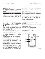
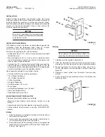
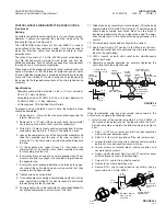
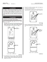
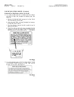
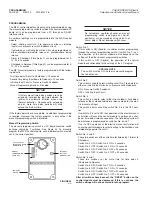

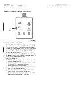

6. Continue holding the DELAY and RESET buttons while the
module powers up (3 beeps while all LEDs are on). When
ONLY the green POWER LED remains flashing, the DELAY
and RESET buttons may be released, see Figure 34d.
FIGURE 34d
Note:
If the BATTERY LED continues flashing, perform the
following procedure:
a. Remove the internal battery
b. Allow the module to remain unpowered for at least 30
seconds
c. Follow steps 4 through 6.
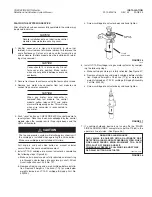
7. Re-install the cover, making sure the cover seal is clean and
correctly in place (not twisted). A small amount of silicone
lubricant will improve the seal effectiveness.
FUNCTION TEST
Before conducting the following FUNCTION TEST, connect the
internal battery to the front cover using the battery extender cable
assembly, Part No. 426604, and connect the Extender Test Cable
Assembly, Part No. 426601, to the terminal strip inside the back
box and the mating terminal strip inside the cover. (The Extender
Test Cable Assembly allows separation of the cover from the back
box while maintaining circuit integrity.
Depress the “RESET” button on the control module. This will set
the module to normal. Reset will be acknowledged by the control
module with short pulses from the sounder.
At this point, the GREEN Power LED should be the only LED
pulsing.
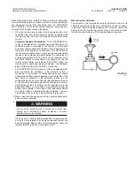
When performing any of the functional tests, make certain the
release circuit tester, Part No. 423541, is attached to the gas
motor connector.
The following tests will verify that the system will operate upon
receiving an electrical signal from a detection device (simulated
fire condition) or when actuated using an electric pull station. The
accuracy of the time delay setting(s) will also be verified during
this test. If the system is connected to a vehicle shutdown device,
the vehicle should be left running during this test to verify that the
shutdown device is functioning. If noted results are not attained,
refer to the Troubleshooting Section of this manual for corrective
action.
Detection Circuit Functional Test
NOTICE
Before conducting the functional test, each
time delay setting must be known.
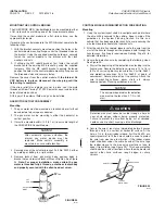
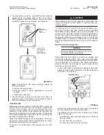
Before conducting the functional test, remove the module cover
and install the extender cable(s). Then, using a digital Ohmmeter,
measure the resistance between terminals 3 and 4 with the detec-
tion wire connected. The resistance value should read approxi-
mately 4.7K ohms. This will verify the circuit is intact and the
end-of-line resistor is connected.
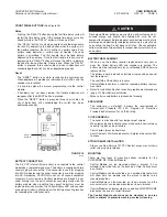
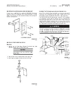
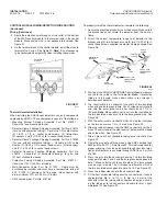
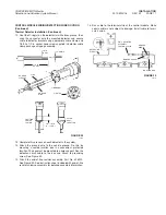
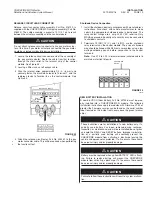
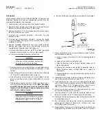
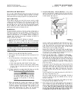
1. Using a short length of insulated wire stripped at both ends,
hold one end of the wire to Terminal 3 and hold the other end
to Terminal 4. See Figure 35.
FIGURE 35
002770
Hold the wire on the terminals for a time which is shorter than
the time programmed in for the first time delay.
The following will take place while the jumper wire is being
held on the terminals:
• The RED Alarm LED and sounder will pulse at a rate of two
times per second
• The first time delay cycle will start
• The alarm relay will activate (non-latching)
!
CAUTION
INSTALLATION
2012-MAY-18 REV. 02 PAGE 21
CHECKFIRE MP-N Electric
Detection and Actuation System Manual
DETECTION CIRCUIT
TERMINALS 3 AND 4
4
DETECTION
CIRCUIT
WIRING
JUMPER
3
009028
CONTINUE
HOLDING WHILE
MODULE
POWERS UP
REFER TO THE
PROGRAMMING
SECTION TO
CHANGE TIME
DELAY SETTINGS
009027


