


PRE-INSTALLATION GUIDELINES (Continued)
2. Do not install the linear detection wire within 12 in. (30 cm) of
areas which will become extremely hot during operation, such
as engine block, exhaust manifolds, turbochargers. etc.
Note: Maximum installed ambient temperature at the wire
location is 221 °F (105 °C).
3. Avoid routing detection wire directly across an opening.
Where possible, install detection wire above the hazard area
or around the perimeter of a hazard compartment to react to
escaping heat. Do not allow struts, frame members, etc. to act
as heat shields between the hazard and the detection wire.
4. Avoid areas where the detection wire may be damaged, such
as outside the vehicle, near moving parts, in areas where
rocks or debris may be thrown by wheels, or in the way of
maintenance personnel.
5. To reduce its accessibility to damage, use only as much
detection wire as is necessary to cover the hazard area.
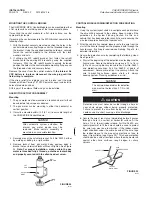
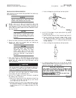
6. The minimum bend radius for detection wire must not be less
than 2 1/2 in. (65 mm).
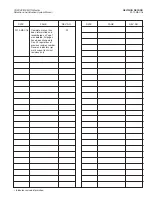
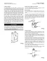
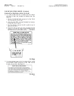
Thermal Spot Detector Selection and Placement
Thermal detectors are used when single point detection is
required. They are selected by temperature range relative to the
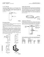
hazard temperature. Table 1 indicates the thermal spot detector
rated operating temperature required according to the maximum
hazard temperatures.
Thermal Spot
Detector
Maximum
Rated Operating
Hazard
Temperature Temperature
Detector
°F
(°C)
°F
(°C)
Color
Part No.
_____________
___________
____
_______
270
(132)
234
(112)
Blue
416218
325
(163)
280
(137)
Red
416219
360
(182)
312
(155)
Red
416220
TABLE 1
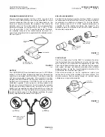
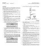
The placement of thermal spot detectors should be based on the
following requirements:
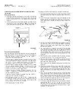
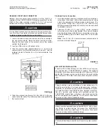
1. They can be wired directly to the control module using
approved cable. Cable must have a temperature rating of
392 °F (200 °C) minimum, 16-18 gauge, two conductor with
drain, minimum O.D. of 0.230 in. (5.8 mm). Again, placement
of the detectors should allow for incoming and outgoing wire
connections.
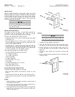
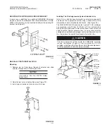
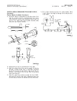
2. Secure the detector with the provided bracket and clamps.
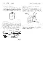
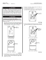
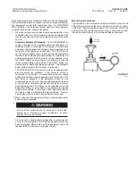
Pneumatic/Linear Detection Tubing
1. When mounting tubing and responder, make certain they are
not in areas subject to damage.
2. Avoid routing detection tubing directly across an opening.
Where possible, install detection tubing above the hazard
area or around the perimeter of a hazard compartment to
react to escaping heat. Do not allow struts, frame members,
etc., to act as heat shields between the hazard and the detec-
tion tubing.
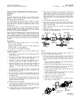
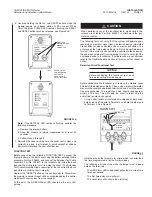
3. The detection tubing assembly is 35 ft (10.7 m) long. If more
than 35 ft (10.7 m) is required, additional assemblies can be
added. See wiring diagram details on instruction sheet
included with each Pneumatic/Linear Detection Shipping
Assembly.
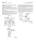
System Layout
Once the system components have been selected and their loca-
tions have been determined, sketch the layout of the system. This
sketch should include the location of the components, as well as
the proposed detection wire routing, thermal detector locations,
and pneumatic actuation hose routing. Also, indicate areas where
the wire must pass through bulkheads so that there is an accept-
able routing from one hazard to the next. This sketch should be as
precise as possible to avoid any unforeseen installation problems
later.
SYSTEM PLANNING
2012-MAY-18 REV. 02 PAGE 11
CHECKFIRE MP-N Electric
Detection and Actuation System Manual


