INSTALLATION
2012-MAY-18 REV. 02 PAGE 19
CHECKFIRE MP-N Electric
Detection and Actuation System Manual
NO
C
NC
14
15
16
SHUTDOWN
RELAY
RELEASE CIRCUIT
7 8
BLACK/WHITE
WIRE
RED/
GREEN
WIRE
7
8
+
–
RELEASE CIRCUIT LEAD CONNECTOR
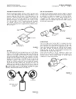
Release circuit connector cable assembly, Part No. 416129, is
supplied with the CHECKFIRE MP-N shipping assembly (Part No.
416354). The cable assembly is precut to 10 ft (3.1 m) to reach
between the actuator assembly and the control module.
Do not attach release circuit connector to live gas motor actua-
tor at this time. If gas motor actuator is connected, the gas motor
could be actuated accidentally during installation.
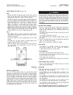
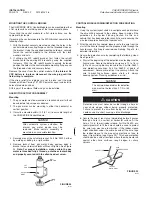
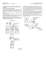
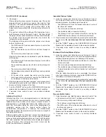
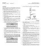
1. Locate the release circuit connector end of the assembly at
the gas motor actuator. Route the cable from that location,
through the strain relief, to the terminal strip at the control
module. See Figure 33.
2. Leaving a little slack, cut off excess cable.
3. Strip the internal wires approximately 1/4 in. (6 mm) and
securely fasten the black/white leads to Terminal 7 and the
red/green leads to Terminal 8 on the control module. See
Figure 33.
FIGURE 33
002767
4. Attach the release circuit tester, Part No. 423541, to the gas
motor connector cable. This will be required when performing
the functional test.
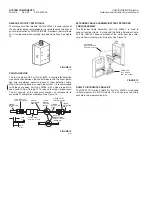
Shutdown Device Connection
1. Install the shutdown device in accordance with manufacturerʼs
instructions. Also check with vehicle manufacturer to make
certain the appropriate shutdown device is being used. The
relay contact ratings are 3 amp @ 30 VDC resistive. Only
MSHA approved intrinsically safe circuitry may be connected
to shutdown contacts.
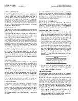
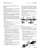
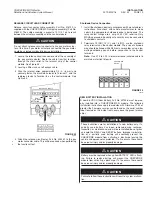
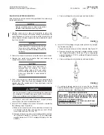
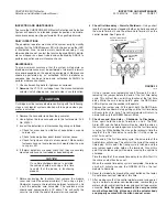
2. Terminals 14 (NO), 15 (C), and 16 (NC), are the shutdown
relay terminals on the control module. The ends of stranded
wire should be tinned with 60/40 rosin core solder, using a low
wattage soldering pencil, before connection to the control
terminals.
Note:
Use 0.13 to 0.25 in. diameter round jacketed cable to
maintain water tight integrity.
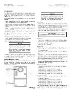
FIGURE 34
000870
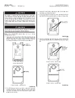
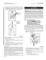
NEW BATTERY INSTALLATION
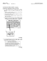
A new 3.6 VDC Lithium Battery, Part No. 427308, must be prop-
erly installed into a CHECKFIRE MP-N module. The following
installation instructions apply to modules with Firmware V1.05 or
greater (the Firmware version can be found on the serial number
label, located on the inside front cover above the green terminal
strip.)
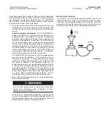
These instructions are for installation of a new battery only. If a
partially used battery has been removed during recharge,
inspection, or maintenance, and will be re-installed, do not press
and hold the DELAY and RESET buttons. Improper re-installa-
tion of a partially used battery will eventually prevent the
CHECKFIRE module from activating a discharge leaving the
vehicle and personnel unprotected. If a fire occurs, there could
be personal injury and/or property damage.
Battery must be replaced when yellow BATTERY LED is flash-
ing. Failure to replace battery will prevent the CHECKFIRE
module from activating a discharge. If a fire occurs, there could
be personal injury and/or property damage.
Failure to follow these instructions will result in system malfunc-
tion.
!
CAUTION
!
CAUTION
!
CAUTION
!
CAUTION

