background image

Operating the Control Panel

45

Instruction Manual – HDMI-UTPRO-0808

Take Key

The Take Key functions much like the Enter Key on a computer keyboard. Pressing the Take Key instructs the system to 
execute or disconnect a switch. Prior to pressing the Take Key, the individual operation components are selected by 
pressing the appropriate keys.

Input Keys (1-8) and Output Keys (1-8)

The Input and Output Keys correspond to the input and output connections on the rear of the enclosure. These keys are 
used to select (or deselect) the inputs and outputs for routing source signals to destination devices as well as for status 
operations. Input Keys are also used for locking and unlocking the control panel. When an Input or Output Key is 
pressed, the channel name (e.g., O_Ch:0003 for Output 3) displays on the LCD. Hold the key down to display the name 
longer.

Note:

 Custom channel names can be created in XNConnect (see page 113).

The Input and Output Keys illuminate depending on the mode (the type of operation) the HDMI UTPro is in:



Blue key

 – indicates that it can be selected as part of the current operation.



White or flashing white key

 – indicates that it has been selected and that further action is required to 

complete the operation. A white key can also indicate routing status. White keys can be deselected. 
When a key is flashing white, it cannot be deselected and does not display label information on the 
LCD when pressed (to clear the operation, press the Cancel Key).



Non-illuminated key

 – is not available for the current operation.

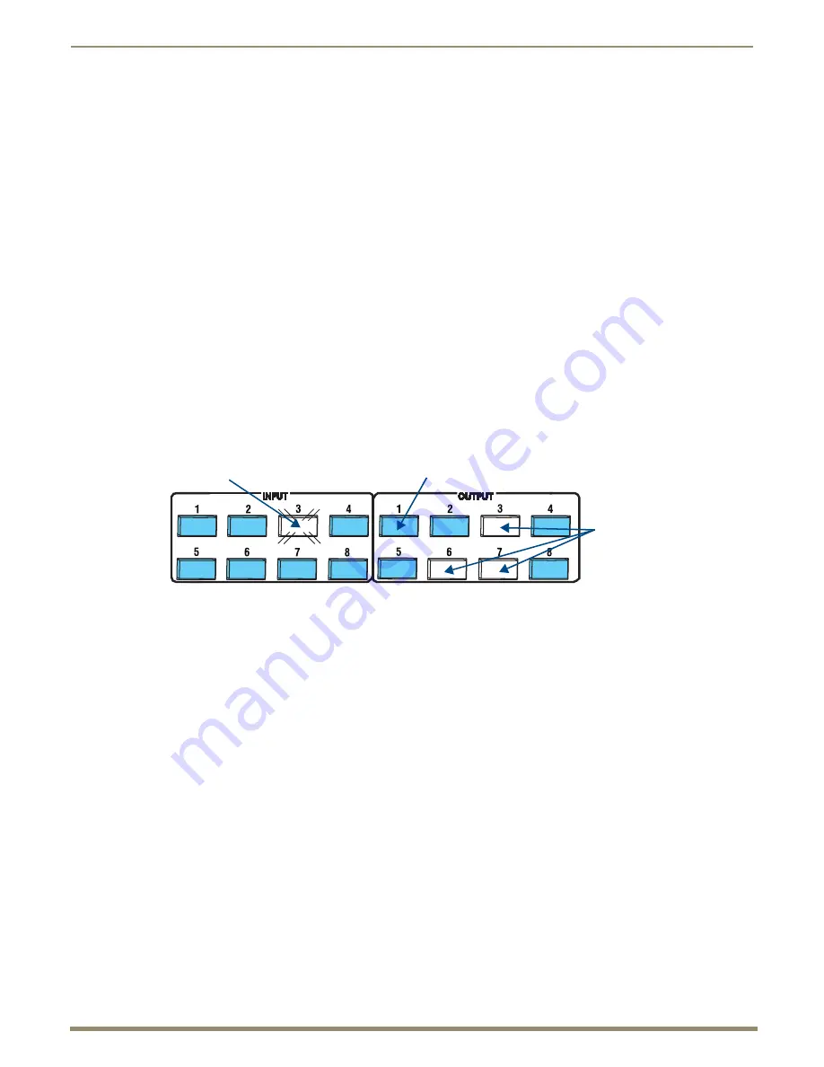
Key State Example

In the Key State example in FIG. 32, Input 3 is flashing white, indicating that it was selected first. Outputs 3, 6, and 7 are 
illuminated white, indicating that they have also been selected (and can be deselected). The switch from Input 3 to 
Outputs 3, 6, and 7 will be executed when the Take Key is pressed.

Power LED

The green Power LED illuminates when the HDMI UTPro is receiving power.

FIG. 32  

Example of key states during Change Mode

Selected key flashing white

Selected keys

Available keys

illuminated white

illuminated blue 

Содержание HDMI-UTPRO-0808

Страница 1: ...Instruction Manual Matrix Switcher with Integrated Transport HDMI UTPRO 0808 HDMI UTPro 8x8 Matrix Switcher HDMI UTPRO RX HDMI UTPro Receiver REV F 01 07 2014...

Страница 2: ...switch on and off any load that is properly connected to our lighting Products as long as the AMX lighting Products are under warranty AMX also warrants the control of dimmable loads that are properly...

Страница 3: ...iagnostics Programmer s Interface 23 Installation and Setup 24 Site Recommendations 24 General Hazard Precautions 24 Unpacking 25 System Diagram 26 Rack Installation and System Setup 26 Important Twis...

Страница 4: ...9 Determining the IP Address of the HDMI UTPro 69 Admin Menu 71 Control Page 71 Device Configuration Page 72 Security Settings 74 IP Settings 75 Port Settings 76 Editing the Clock Manager Settings 77...

Страница 5: ...pendix B Programmer s Interface for System Diagnostics 106 System Component Information 106 Using BCS to Access System Diagnostic Information 107 Splash Screen Examples 108 Appendix C Managing Configu...

Страница 6: ...s and conductive work mats are specifically designed for this purpose Anyone performing field maintenance on AMX equipment should use an appropriate ESD field service kit complete with at least a diss...

Страница 7: ...ort For products with multiple power supplies in each unit make sure all power supplies are turned on simultaneously Use surge protectors and or AC line conditioners when powering AMX products Only us...

Страница 8: ...on multiples dans chaque unit soient allum s simultan ment Servez vous de protecteurs de surtension ou de conditionneurs de lignes courant alternatif lorsque vous mettez les appareils AMX sous tension...

Страница 9: ...ing notice be brought to the attention of the users of this product Note This equipment has been tested and found to comply with the limits for a Class A digital device pursuant to part 15 of the FCC...

Страница 10: ...Department of Energy Other products mentioned herein may be the trademarks of their respective owners Warnings and Cautions This manual uses the following conventions and icons to draw attention to ac...

Страница 11: ...d with the most common EDID settings to ensure proper functionality with source devices Features the AMX EDID Programmer allowing specific display EDID settings to be custom loaded on each input Globa...

Страница 12: ...ons briefly introduce the hardware on the rear panel Power Receptacle The universal power receptacle is in the lower left hand corner on the rear of the enclosure Maximum power specifications are on t...

Страница 13: ...the Serial RJ 12 connector and its LEDs are to the right of the power receptacle An ID push button not required for installation which places the system in ID mode for setting the NetLinx ID device o...

Страница 14: ...The number for the HDMI matrix switching output connector and number for the HDMI transport input connector must match for each patch cable UTP RJ 45 transport output connectors OUT 1 8 provide conne...

Страница 15: ...w is recommended see the section on Airflow Restriction on page 24 HDMI UTPRO RX Components The front of the HDMI UTPRO RX Receiver has an LED Power indicator The rear components on the HDMI UTPRO RX...

Страница 16: ...Receiver Module FG IR03 The IR03 connects to the IR Rx jack on the HDMI UTPRO RX allowing IR signals to be received from a compatible IR remote control like the UDM RC05 The IR03 allows the HDMI UTPR...

Страница 17: ...o execute presets LCD Display The LCD displays the Function menu The Function menu and its submenus access the different modes and lists used to control the system Cancel Key The Cancel Key clears an...

Страница 18: ...I Specifications table for complete specifications see page 19 HDMI Transport Input Connectors The HDMI inputs INPUT 1 8 accept HDMI patch cables provided from the HDMI matrix switching outputs OUT 1...

Страница 19: ...esults have been seen using a Cat6 coupling device for attaching the cables together even when using lower rated Cat5e cabling If running cables together then screened cabling should be used to reduce...

Страница 20: ...cation Resolution Refresh Rate Max ID 1 1920x1080 This is the preferred timing identified in the EDID 60 Hz ID 2 1680x1050 60 Hz ID 3 1600x1200 60 Hz ID 4 1280x800 60 Hz ID 5 1280x720 60 Hz ID 6 1280x...

Страница 21: ...6 9 VIC 20 1920x1080i 50 Hz 16 9 VIC 21 720 1440 x576i 50 Hz 4 3 VIC 22 720 1440 x576i 50 Hz 16 9 VIC 29 1440x576p 50 Hz 4 3 VIC 30 1440x576p 50 Hz 16 9 VIC 31 1920x1080p 50 Hz 16 9 VIC 32 1920x1080p...

Страница 22: ...he HDMI UTPro WebConsole chapter on page 69 for details Use NetLinx SEND_COMMANDs to configure and control the HDMI UTPro Refer to the HDMI UTPro NetLinx Programming chapter on page 83 for programming...

Страница 23: ...Devices The HDMI UTPro is compatible with a number of AMX control devices For control programming information see the instruction manual for the specific interface Third Party Controllers A third par...

Страница 24: ...atible with the manufacturer s maximum rated ambient temperature In a closed or multi unit rack assembly the operating ambient temperature of the rack environment may be greater than the ambient room...

Страница 25: ...on includes AMX HDMI UTPRO 0808 Twisted Pair Dist Kit Quick Start Guide Shipping boxes are marked as Box __ of __ where the first blank is the box number and the second blank is the total number of bo...

Страница 26: ...ed items for rack installation Enclosure Standard EIA 19 in 48 26 cm rack Rack ears with 8 screws per kit Screwdriver Screws that fit your rack for mounting the enclosure Standard US power cord if shi...

Страница 27: ...ng power to its source and destination devices Installation Procedure A flow chart showing the installation sequence is in FIG 9 The procedure on page 28 provides general steps with references to deta...

Страница 28: ...th a NetLinx Controller see Establishing an Ethernet 10 100 Network Connection on page 33 8 Optional for the Serial port RJ 12 RS 232 Establish serial communication with an external serial control dev...

Страница 29: ...to 60 meters before they must be separated over the remainder of the run Cat6a and Cat7 which are shielded by definition can be bundled for the entire 100 meter run Important DXLink twisted pair cabl...

Страница 30: ...etween the HDMI UTPro enclosure and its Receivers Service loops or coils of the cable will reduce the overall cable performance and should be minimized whenever possible The total run of a UTP cable i...

Страница 31: ...peat Steps 1 through 3 for the remaining source devices be sure each patch cable is connected to corresponding numbers 2 to 2 3 to 3 etc The number for the HDMI matrix switching output connector and n...

Страница 32: ...connect an IR Emitter to the HDMI UTPRO RX Receiver 1 Connect an IR01 IR Emitter cable FG IR01 to the IR Tx port on the Receiver 2 Run the other end of the IR TX cable to the display device and locat...

Страница 33: ...nfigured to open port 1319 for remote connectivity over UDP Cable Requirements for LAN Connection or a PC s NIC card An RJ 45 cable either crossover or straight through is required to connect the HDMI...

Страница 34: ...assign an IP address If you power down and power back up the DHCP server will reassign the IP address which may or may not be the same address it assigned before To prevent the possibility of the IP...

Страница 35: ...ole from which you must then change the DHCP IP address to the static address provided by your Network Administrator before you connect the HDMI UTPro directly to the LAN Determining IP address for HD...

Страница 36: ...DMI UTPro WebConsole chapter on page 69 Note For additional information on Zero Config or the WebConsole see the Programming Guide NetLinx Integrated Controllers at www amx com Serial Port RJ 12 The S...

Страница 37: ...rt connection to a NetLinx Master Serial port as DTE interface with female connection Serial port as DCE data circuit terminating equipment interface with male connection FIG 22 Serial RJ 12 port on t...

Страница 38: ...e or the end cable adapter into the serial port on the external device 4 Check to be sure that the device s serial port settings and serial port settings on the enclosure see table to the right corres...

Страница 39: ...ntroller documentation for operating instructions Note Attaching an external serial controller is an optional installation procedure Attaching Control Port to an External Serial Controller Optional An...

Страница 40: ...cuit We strongly recommend using a dedicated line for the system s power To avoid an overload note the power consumption rating of all the equipment connected to the circuit breaker before applying po...

Страница 41: ...the test switch to verify the system is working correctly disconnect the test switch and clear the sink key cache see page 68 before finishing the installation We suggest executing a test switch to v...

Страница 42: ...modem serial cable to a serial control device running a terminal emulation program The settings on the PC serial communication software and the enclosure must correspond to each other When using a ter...

Страница 43: ...r within the enclosure Check all link and signal connections on the rear of the enclosure to make sure everything is physically set up correctly Check all power switches on the source and destination...

Страница 44: ...ous command options e g Status Disconnect etc The Function Key can be pressed at anytime to return the display to the Function menu Control Dial The Control Dial scrolls through menu options and adjus...

Страница 45: ...tput Keys illuminate depending on the mode the type of operation the HDMI UTPro is in Blue key indicates that it can be selected as part of the current operation White or flashing white key indicates...

Страница 46: ...iled information and instructions on the individual modes are provided in the remainder of the chapter Use the Control Dial and Select Key to navigate the Function menu submenus and lists The menus ar...

Страница 47: ...em in Change Mode The control panel must be in Change Mode to execute switches While in Change Mode select the Input and Output s Keys followed by the Take Key to execute switches see page 48 Virtual...

Страница 48: ...press the Take Key to execute it For new installations we recommend that before attaching all inputs and outputs you execute a test switch routing Input 1 to Output 2 the example used in the instructi...

Страница 49: ...fault virtual matrix when the power is cycled For information on changing the default virtual matrix see page 57 The example below assumes additional VMs have been created and provides instructions fo...

Страница 50: ...d white and deselected blue state before pressing the Take Key For more information see page 45 Once the control panel is in Disconnect Mode inputs and outputs can be selected and deselected by pressi...

Страница 51: ...ut Keys turn blue 4 Press the Input Key that corresponds to the input you want to check The selected Input Key turns white and any Output Keys receiving the input signal also turn white Or Press the O...

Страница 52: ...h the Control Dial 4 Press the Select Key The Global Preset submenu appears 5 Scroll to Define Global 6 Press the Select Key again to choose Define Global The Define Global list appears 7 Scroll to Gl...

Страница 53: ...ress the Select Key The Global Preset submenu appears 4 Press the Select Key again to choose Execute Global The Execute Global Preset list appears 5 Scroll to Global Preset 3 6 Press either the Select...

Страница 54: ...e local presets have been defined as part of the configuration file the new file must be loaded to the system s CPU and reloaded to the control panel see page 58 Make sure the control panel is on the...

Страница 55: ...rol panel The panel remains locked if the power is cycled Locking the Control Panel The following example uses the default password of 1 2 3 4 1 entered using the first five keys in the top row Inputs...

Страница 56: ...ey 1 default password The panel unlocks and returns to the Function menu Setup Options The following options are available under the Setup Options submenu Software Version to display software version...

Страница 57: ...em will revert to that virtual matrix each time the system is powered up even if you changed the virtual matrix using the V Matrix list during normal operation The power must be cycled before the defa...

Страница 58: ...one of the Configure menu options see the XNConnect Help file If the configuration file was loaded to the system s CPU using any of the following options the control panel will need to reload the fil...

Страница 59: ...to establish connection see page 39 To enable error code reporting 1 Enter ERR 1 The system responds with V Note If the power is cycled you will need to enable error code reporting again To turn off...

Страница 60: ...ed entertainment content to be switched freely while high resolution capabilities 1920x1200 provide the advantage of being able to use this solution to switch high resolution computer images or a comb...

Страница 61: ...source devices and the HDMI UTPro inputs each support a specific maximum number of sinks HDCP Source Device Each source has a specific number of sinks repeaters and or destination devices that it can...

Страница 62: ...limit Four Examples of HDCP Source Sink Support FIG 35 through FIG 38 The next four figures illustrate system setups in which the source device supports a maximum of 3 sinks downstream of the first r...

Страница 63: ...g your preferred method of control send a command to make sure all outputs are disconnected from the input for the source device 4 On the PC open a terminal emulation program e g TeraTerm PuTTY or Hyp...

Страница 64: ...stallation extra repeaters etc continue with the next one until full system capabilities are mapped out The next process works for determining if additional sinks are supported by the source device up...

Страница 65: ...will need to clear the input s sink key cache and then persist the cleared state to eliminate the key s before routing the source to any of the destinations for instructions see page 68 Control Sugge...

Страница 66: ...ome sources can choose what signal types audio and video they are sending to a destination based on the destination s EDID Therefore connecting the source directly to the destination may work fine bec...

Страница 67: ...to 3 TXD and 3 TXD to 2 RXD 3 Plug the other end of the serial cable into the serial port on the PC 4 Open a terminal emulation program e g TeraTerm PuTTY or HyperTerminal 5 Select the COM port and se...

Страница 68: ...ds to Clear Persistence of the Sink Key Cache To clear persistence of sink key cache using SEND_COMMANDs 1 Enter SEND_COMMAND dvUTPro INSTAGATECLEAR clears the cache and disconnects all currently rout...

Страница 69: ...work In essence it allows you to set up a network without any configuration Accessing Zero Config Information in NetLinx Studio 3 0 NetLinx Studio version 3 0 or higher features a Zero Config tab in t...

Страница 70: ...the same subnet e g 192 168 X X The initial view is a display only view of the IP Settings page If the IP Setting page does not open see the WebConsole Troubleshooting section on page 80 Note that the...

Страница 71: ...Receivers must be connected This page provides a rudimentary control method if a master connection is not available Control Commands Note Only ASCII printable characters are supported To send commands...

Страница 72: ...appears in the Replies field on the right Click Refresh to receive new replies notifications in the Replies field New replies are added to the bottom of the list Click Clear to clear the Replies fiel...

Страница 73: ...e available mode settings for each are described in the following table Click Accept to save the changes Changes on this page take effect immediately Click Cancel to exit the page without saving any c...

Страница 74: ...hanges Login Information Use the Login Information fields to specify a user name and password Login information is required only if one or more of the Security Settings are enabled FIG 48 Security Set...

Страница 75: ...Configuration Manager the IP Settings page is displayed and can be edited as necessary IP Settings Select IP Settings from the Admin drop down menu to open the IP Settings page FIG 50 Use the options...

Страница 76: ...page IP Settings DHCP Click to toggle the DHCP setting on the HDMI UTPro default enabled When the DHCP check box is not selected a static IP address with the appropriate subnet must be entered When t...

Страница 77: ...Timezone and click Accept When Network Time is selected you must click Accept the Daylight Saving tab and the NIST Servers tab become available their settings are modified on separate pages Note If us...

Страница 78: ...aylight Savings Use these radio buttons to turn daylight savings time on and off default Off Offset Use these drop down menus to specify the amount of time to offset the clock for daylight savings Sta...

Страница 79: ...To adjust NIST Servers settings in the Clock Manager 1 From the Admin drop down menu select Clock Manager or select Mode from the Clock Manager submenu 2 Under Time Sync select Network Time and click...

Страница 80: ...e functioning Ping the system i e at the DOS prompt enter ping XXX XXX XX XX where XXX XXX XX XX is the HDMI UTPro IP address For an example of a typical response showing verification of communication...

Страница 81: ...n exception in the Proxy Setting dialog box The instructions below apply to Internet Explorer To change these settings in another browser consult its Help file To add an exception to the proxy setting...

Страница 82: ...ep 4 If the Proxy server box is not checked check it before going to Step 4 4 Click Advanced The Proxy Settings dialog box opens 5 In the Exceptions field enter the appropriate HDMI UTPro s IP address...

Страница 83: ...tput control strings to a connected device Port 3 Reserved for future use FIG 56 NetLinx Studio Online Tree indicating HDMI UTPro and connected HDMI UTPRO RX Receivers HDMI UTPRO RX Receiver number au...

Страница 84: ...t Port 7 device number 05507 HDMI UTPRO RX connected to UTP Output Port 8 device number 05508 Therefore it is important to avoid assigning device numbers that will conflict with this auto numbering sc...

Страница 85: ...D dvUTPro CL0I3O2 3 4 5 or SEND_COMMAND dvUTPro CL0I3O2 3 4 5 Connect input 3 to multiple outputs on level 0 virtual matrix 0 Note Multiple outputs in commands can be entered with either comma or spac...

Страница 86: ...firmware version of various HDMI UTPro components Syntax SEND_COMMAND DEV FWVERSIOND D Variables D hub component description HUB MAIN The return value is FWVERSION version if the D and component descr...

Страница 87: ...erial communication parameters Syntax SEND_COMMAND DEV SET BAUD baud parity data stop Variables baud baud rates are 115200 57600 38400 19200 9600 4800 2400 1200 default 9600 parity N none O odd E even...

Страница 88: ...signed to the target HDMI UTPro By default the Device Number assigned to the HDMI UTPro in NetLinx Studio is 05500 The Device Number can be viewed edited in the HDMI UTPro Configuration Manager Device...

Страница 89: ...been changed use the Online Tree to determine the new ID 5 Review the File Connection Address and Target Device information before you send the KIT file 6 Important Be sure to select the Reboot Devic...

Страница 90: ...e NetLinx Integrated Controllers available at www amx com Caution If for any reason your KIT file transfer should fail continue to retry the transfer until you are successful Do not reboot the HDMI UT...

Страница 91: ...the HDMI UTPro is automatically designated a device number based on the device number of the HDMI UTPro to which it is connected and on the number of the UTP OUTPUT port 1 8 on the HDMI UTPro to whic...

Страница 92: ...SEND_COMMAND DEV FWVERSION Example SEND_COMMAND dvRX FWVERSION The return value is FWVERSION version RP P Sets the protocol used by the IR remote The RX can support a number of different remote units...

Страница 93: ...unction 21 is loaded an Enter will follow the number If the channel is greater than or equal to 100 then IR function 127 or 20 whichever exists is generated for the one hundred digit Uses CTON and CTO...

Страница 94: ...XCH send commands in tenth of a second increments Syntax SEND_COMMAND DEV CTON time Variables time 0 255 Given in 1 10th of a second increments Default is 5 0 5 seconds Example SEND_COMMAND dvRXIR CT...

Страница 95: ...e IR code as 3 4 3 enter Mode 1 Example x x x enter SEND_COMMAND dvRXIR XCH 3 Transmits the IR code as 0 0 3 enter SEND_COMMAND dvRXIR XCH 34 Transmits the IR code as 0 3 4 enter SEND_COMMAND dvRXIR X...

Страница 96: ...tion parameters The port sends the parameters to the device that requested the information Syntax SEND_COMMAND DEV GET BAUD Example SEND_COMMAND dvRXRS232 GET BAUD The port responds with port baud par...

Страница 97: ...emporarily sets the RX serial port s communication parameters to 19200 baud no parity 8 data bits 1 stop bit TSET BAUD Set the serial communication parameters Syntax SEND_COMMAND DEV TSET BAUD baud pa...

Страница 98: ...icable IRL file from www amx com Partners Search Devices to your PC 3 Verify that an Ethernet ICSNet cable is connected from the NetLinx Master to the network and that the HDMI UTPro is connected to t...

Страница 99: ...e s you want to transfer are not included in the open Workspace This tab consists of a display of the different types of files that can be transferred to the Master or System devices on the bus 3 Sele...

Страница 100: ...o determine the device s assigned ID if it has been changed 7 At this point the selected IRL File and mapping information is indicated in the File list FIG 66 8 Click OK to close the Select Files for...

Страница 101: ...a display device the result would be either a badly distorted image or no image at all To address these issues the HDMI UTPro comes with one EDID EEPROM chip per input connector which has been pre lo...

Страница 102: ...isplays a format incompatibility message analysis or editing of their EDID data may be necessary prior to using the EDID Programmer A variety of freeware tools can be found on the web to help with the...

Страница 103: ...solution Cards with 2 HDMI connectors 2 DVI connectors 2 VGA connectors or cards with a combination of any two of the three HDMI DVI and VGA are also acceptable To install EDID Programmer software 1 L...

Страница 104: ...HD 15 to DVI cable attach a DVI to DVI barrel attach a DVI to HDMI cable attach to the destination device Note The EDID information is passed but not video signals Writing EDID Data to HDMI Matrix Sw...

Страница 105: ...nd at www amx com products EDIDLibrary asp The first group of files use 1080p VIC 16 as the preferred native video resolution The second group of files use 720p VIC 4 as the preferred native video res...

Страница 106: ...h screen displays information only for the enclosure that is connected directly to the PC AMX reserves the right to add to the contents of the splash screen at any time without notice Verbosity i e wo...

Страница 107: ...69 on page 106 Using BCS to Access System Diagnostic Information Instructions are provided for accessing the lowest level of verbosity for all components and for accessing a specific level of verbosi...

Страница 108: ...re four examples of splash screen information that could be displayed when different verbosity component settings are specified Depending on the amount of detail provided you may need to scroll to see...

Страница 109: ...ype Block mode FP port 115200 8 1 N NE S interface 3 detected type BCS mode RS232 port 9600 8 1 N E NS interface 4 detected type Neuron bridge undetected scrv3i4 4 Hardware Boards detected switching d...

Страница 110: ...el password and customizing input and output channel names for control display e g in the APWeb interface Automatic Configuration An HDMI UTPro system is automatically configured when the system gener...

Страница 111: ...from www amx com 1 Close all other applications currently running on your PC 2 Go to www amx com and login as a Dealer to download XNConnect 3 Optional Select the Release Notes to read about the soft...

Страница 112: ...File menu select Save to save the discovered configuration information to the PC 9 From the File menu select Save As and save an xcl file with a new name to the PC This creates a duplicate copy which...

Страница 113: ...es setting the control panel password and configuring local presets For complete coverage of configuration related tasks see the XNConnect Help file Modifying Source and Destination Channel Names If t...

Страница 114: ...Save As and save an xcl file with a new name to the PC We strongly recommend making a duplicate copy every time the file is modified Setting the Control Panel Password The control panel on the HDMI U...

Страница 115: ...st be used to lock and unlock the control panel 7 From the File menu select Save As and save an xcl file with a new name to the PC We strongly recommend making a duplicate copy every time the file is...

Страница 116: ...ll disconnect all outputs it is connected to 9 Repeat Steps 6 7 and 8 for all switches and or disconnects to be included in the preset Note For information on the other buttons and preset modification...

Страница 117: ...he control panel and or disconnect any external controllers to make sure that no switches are executed during the loading of the file If you have not already done so From the File menu select Save As...

Страница 118: ...r is required Typically the default configuration string generated by XNConnect is all that is necessary However certain conditions may warrant a custom string such as the need to limit the VMs that a...

Страница 119: ...e system and out to destination devices For the HDMI UTPro each virtual channel is assigned to a physical connector The virtual input and output channels can then be grouped into virtual matrices that...

Страница 120: ...ent method and the fourth for completing the connector assignments To access the Help file regarding an open dialog box press F1 The Physical Matrix The virtual channels need to be assigned to the phy...

Страница 121: ...he entire procedure three times The first time through creates a new virtual matrix VM 1 The information in brackets indicates the changes required on the subsequent times through for VM 2 and VM 3 No...

Страница 122: ...Sequential Under Channel Type select Sources Only Destinations Only will be selected in Step 17 From the Starting Channel drop down list select the first channel number 1 to be included When you creat...

Страница 123: ...lect the HDMI signal from the Available Signals list 19 Click Assign Signal and click OK The Manage Virtual Matrix Groupings dialog box opens again 20 Under Grouped Connectors check the virtual channe...

Страница 124: ...three VMs created for the example on page 119 using the previous procedure are illustrated in FIG 79 below Note that VM 55 at the bottom of the VM list was the original VM 0 discovered on the system a...

Страница 125: ...0 60 soh 01 21 A 41 a 61 stx 02 22 B 42 b 62 etx 03 23 C 43 c 63 eot 04 24 D 44 d 64 enq 05 25 E 45 e 65 ack 06 26 F 46 f 66 bel 07 27 G 47 g 67 bs 08 28 H 48 h 68 ht 09 29 I 49 I 69 nl 0a 2a J 4a J 6...

Страница 126: ...ation knowledge In the ever changing AV industry continual education is key to success AMX University is dedicated to ensuring that you have the opportunity to gather the information and experience yo...

Отзывы: