Installation and Setup
53
Instruction Manual – DXLink™ Twisted Pair Transmitters/Receiver
Wallplate Transmitters – Attaching Signal/Transport Cables
Important:
If network connection is required
–
before attaching cables, set DIP switch #3 Toggle.
Important:
Do not use the RJ-45 connector on rear for connecting to a standard Ethernet Network.
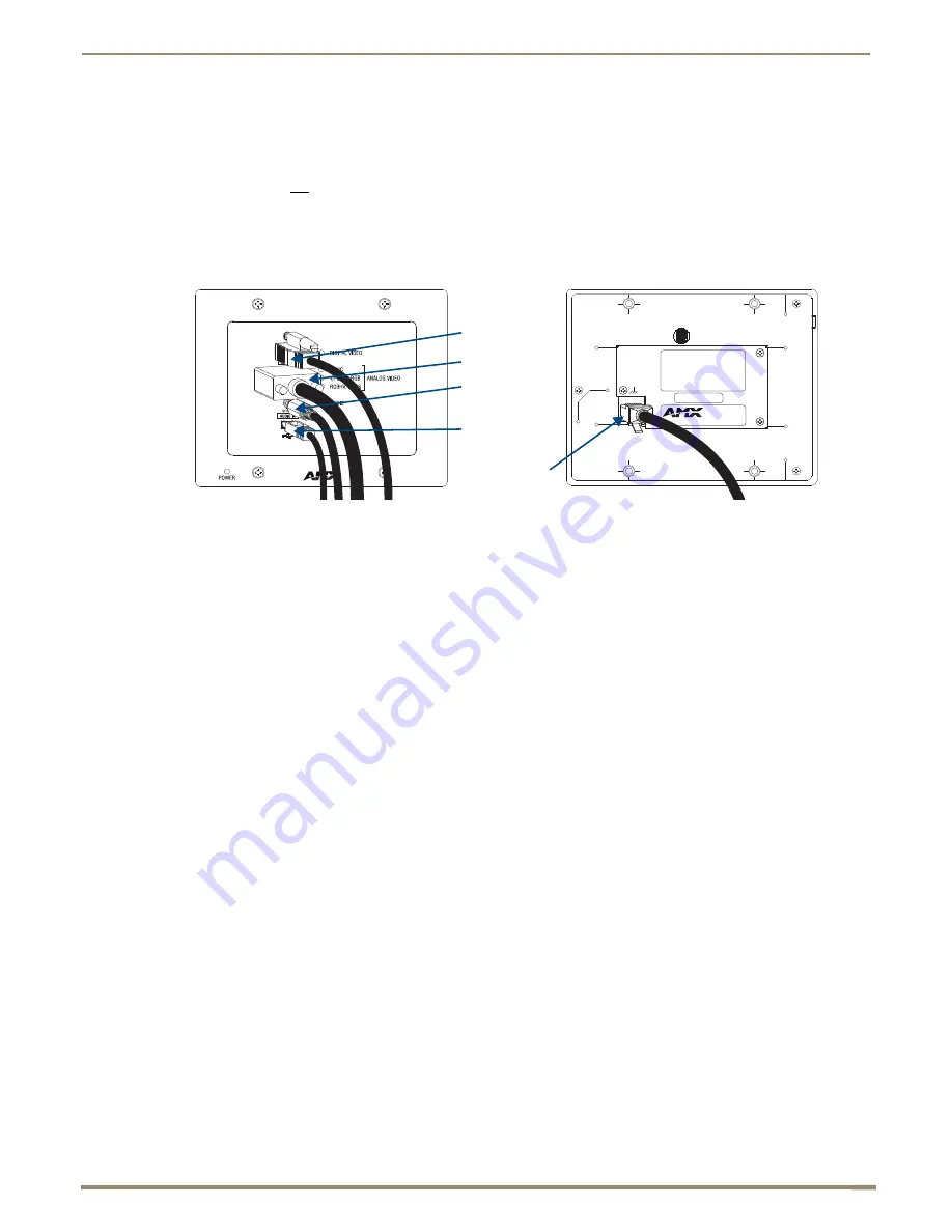
To attach signal and transport cables to a Wallplate TX or Decor Wallplate TX:
1.
Install double-gang back box. (For Wallplate TX mounting options, see page 46. The Decor Wallplate TX uses a
standard US double-gang back box).
Mount Unit, Set DIP switches, and Cable DXLink –
2.
Wallplate TX
–
a.
Remove the four screws from the front that fasten it to the mounting bracket.
b.
Important
– If a network connection is required, set #3 Toggle to ON (see page 45).
c.
Attach bracket (arrows inside point up) to double-gang back box per illustrations on page 46.
d.
DXLink connector – Attach a twisted pair cable from the DXLink Input Board on the switcher through the
mounting bracket to the DXLink (RJ-45) connector on the rear of the unit.
Decor Wallplate TX
–
a.
DXLink connector – Attach a twisted pair cable from the DXLink Input Board on the switcher to the DXLink
(RJ-45) connector on the rear of the unit.
b.
Attach unit to the back box with four screws through the large screw holes.
c.
Important
– If a network connection is required, set #3 Toggle to ON (see page 45).
3.
Wallplate TX
– Reattach unit to the mounting bracket with the four screws removed in Step 2a.
Decor Wallplate TX
–
a.
Check LEDs for normal display (see the table on the next page).
b.
Attach standard decor style front cover plate (customer provided) to the unit.
Cable front (note that connector arrangement differs between unit types) –
4.
HDMI In connector – Attach the HDMI cable from the source device to the HDMI In connector.
5.
Video In connector – Attach the HD-15 cable from the source device to the Video In connector
(for VGA, component, S-Video, and composite pinouts, see page 124).
6.
Stereo Audio In jack (optional) – Plug in the analog audio cable from the stereo audio source into the Stereo Audio
In jack. For audio precedence information, see page 52.
7.
If necessary, set the video and audio formats using SEND_COMMANDs (see page 78).
8.
USB Host port (optional) – Attach USB cable from PC. The port’s default is “enabled.” For USB port information,
see page 26. For USB SEND_COMMAND information, see page 94.
9.
Check LEDs for normal display (see the table on the next page).
Rear view
Front view
DXLink (RJ-45)
connector
HDMI connector
HD-15 connector
Stereo audio
connector
USB connector
FIG. 30
Attach signal and transport cables (Wallplate TX shown)


