Installation and Setup
52
Instruction Manual – DXLink Fiber Transmitters and Receivers
Important:
Compatibility between hardware requires matching model types: multimode to multimode and
single mode to single mode.
Important:
The illustration below shows a Duplex Transmitter wired with dual LC fiber cables. In both Duplex
and Simplex hardware: for each LC fiber cable, be sure to verify that the individual wire from the transceiver’s
TX label on one end of the run connects to the transceiver’s RX label on the other end.
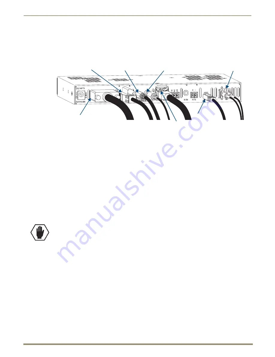
To attach signal, transport, and control cables to the DXLink Fiber TX:
1.
Video In connector – Attach the HD-15 cable from the source device to the Video In connector (for pinouts for
VGA, component, S-Video, and composite, see page 128).
2.
HDMI In connector – Attach the HDMI cable from the source device to the HDMI In connector.*
3.
When attaching a fiber optic cable:
a.
Clean the end face on the fiber cable following the manufacturer’s recommendations.
b.
Fiber optic transceiver – Remove the dust plug (save for further use).
c.
Attach the cable to the fiber optic transceiver** (for transport to the switcher or directly to the RX). Always
grasp the fiber connector housing to plug (or unplug) a fiber optic cable (depending on the housing, a click may
be heard; if not, lightly tug to be sure the connection is tight).
4.
Digital Audio In jack (optional) – Insert the S/PDIF (RCA) plug on the digital audio cable from the digital audio
source into the Digital Audio In jack. For audio precedence information, see page 51.
5.
Stereo Audio In jack (optional) – Plug in the analog audio cable from the stereo audio source into the Stereo Audio
In jack. For audio precedence information, see page 51.
* DVI cable can be used instead (via a DVI-to-HDMI cable adapter).
** When cabling a simplex transceiver, we recommend covering the unused port.
6.
ICS LAN 10/100 connector (optional) – Attach a twisted pair cable from this connector to a LAN. Note that the
#1 Toggle on the DIP switch
must
be set to
ON
to enable this port.
7.
Local Out port (optional) – On the front of the unit, attach an HDMI cable from a local monitor to the Local Out
(HDMI) connector.
8.
Program port (optional) – On the front of the unit, attach a USB mini-B cable from a PC to the Program port.
9.
USB Host port (optional) – Attach USB cable from a PC to the Host USB-mini A/B port. The port’s default is
“enabled.” The USB LED on the front monitors this port. For USB support information, see page 26. For USB
SEND_COMMAND information, see page 93.
10.
If necessary, set the video and audio formats using SEND_COMMANDs (for NetLinx programming information,
see page 77).
Note:
When digital audio and/or analog stereo audio cables are plugged into the TX, the Audio LEDs on the
front of the units turn green to show that audio is present and is being incorporated into the HDMI line and is
also available on the DXLink Fiber RX at the Audio Out connector.
Note:
The ID Pushbutton places the unit in ID Mode for setting the NetLinx ID (device only) and provides
additional functionality, such as placing the device in Static IP Mode or DHCP Mode. For complete
information, see page 68.
FIG. 20
Attach signal and control cables
HDMI In connector
Stereo Audio In jack
USB port
ICS LAN 10/100 connector
Digital Audio In jack
Video In connector
Fiber optic transceiver
Caution:
When you make the connection in Step 6, be careful not to create a network loop (see page 43).


