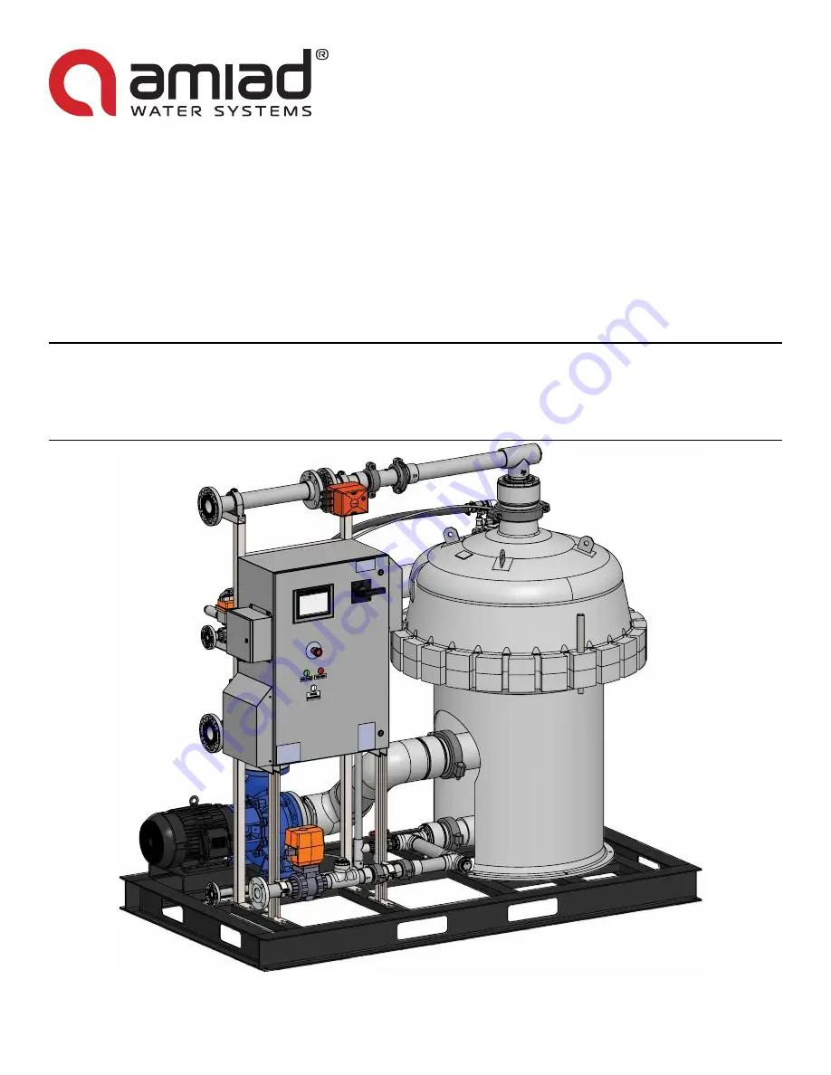
TEQUATIC
™
PLUS F-150 FILTER, C-SERIES SKID
INSTALLATION, OPERATION, AND MAINTENANCE MANUAL
AMIAD WATER SYSTEMS
Revision 3, September 2019
Страница 1: ...TEQUATIC PLUS F 150 FILTER C SERIES SKID INSTALLATION OPERATION AND MAINTENANCE MANUAL AMIAD WATER SYSTEMS Revision 3 September 2019 ...
Страница 2: ... 2 Product Tank 13 2 5 3 External Alarm 13 2 5 4 Flow Meter 13 2 5 5 Feed Pump 14 2 6 Piping and Instrumentation Diagrams 15 2 6 1 Base Diagram 15 2 6 2 Options Diagram 16 3 Controls Overview 17 3 1 Home Screen 17 3 1 1 Manual Controls 18 3 1 2 Message Center 18 3 2 Main Settings Screen 18 3 2 1 Pump Settings 19 3 2 2 Valve Settings 19 3 2 3 Tank Settings 20 3 2 4 Startup Settings 20 3 2 4 1 Gener...
Страница 3: ...lter or Brushes 35 5 2 Troubleshooting 38 6 Spare Parts 40 6 1 Filter Housing Components 40 6 2 Plumbing Components 42 6 3 Controller Components 44 7 Schematic 46 Questions If you have questions or need more information about TEQUATIC PLUS Filters please contact Amiad Water Systems Amiad USA INC 120 Talbert Road Suite J Mooresville NC 28117 800 648 9260 650 800 7818 E mail infousa amiad com Websit...
Страница 4: ...age please read and understand all of the safety precautions and instructions in this section and throughout this manual before servicing or operating this equipment Personnel responsible for system operation and or maintenance should attend all available safety and operator training courses Procedures safeguards and training should be appropriate for the types of hazards present Always disconnect...
Страница 5: ...ices in pipes and equipment carrying hot water to avoid thermal burns Verifying the filter assembly and cleaning assembly are properly installed before operating the system To avoid damage or hammering expel all air from the housing and piping before startup Do not start the system with filtrate line open This will result in premature plugging of the filter membrane Do not over tighten the swing b...
Страница 6: ...in 127 cm Height 85 5 8 in 217 cm Weight Dry 2380 lb 1080 kg Wet 3050 lb 1385 kg Max Particle Size 0 07 in 2mm Filter Element and Typical Flow Rate4 SSC 17 1 80 240 gpm 18 2 54 5 m3 hr SSC 22 1 120 280 gpm 27 3 63 6 m3 hr SSC 27 1 160 320 gpm 36 3 72 7 m3 hr Piping Size Inlet 2 5 in Class 150 Flange DN65 PN16 Filtrate 2 5 in Class 150 Flange DN65 PN16 Concentrate Purge 2 in Class 150 Flange DN50 P...
Страница 7: ...tems 2019 TEQUATIC PLUS F 150 Filter C series Skid 7 Introduction 1 2 1 Dimensions 92 234 50 127 5 8 X4 1 5 7 8 x 4 2 4X Corners Bottom Web 2 7 8 x 4 80 1 2 213 204 25 64 27 69 9 23 12 30 8 20 37 1 2 95 55 1 4 140 84 ...
Страница 8: ...NLET RECIRCULATION PUMP SENSOR BOX SERVICE DRAIN CONCENTRATE PURGE HOT WATER INLET CIP RPM SENSOR AIR BLEED PRESSURE SENSORS 1 3 1 Control System The controller provides the operator interface for the system and controls the operation of the various valves sensors and pump The PLC and VFD are located in the main enclosure with the main disconnect and the HMI screen The small side enclosure is for ...
Страница 9: ...urized This is typically accomplished with a pressure controlled pump The skid controller has a pump control dry contact as well as a feed tank low sensor input Filtrate Effluent The filtrate effluent is the primary treated discharge from the system and should not have appreciable back pressure This line contains a system controlled valve This is typically best served with a holding tank to accomm...
Страница 10: ...s When planning the space consider having extra clearance near the pump to facilitate removal or servicing 2 3 Unpacking the Skid Notice Be careful when working around the filter housing with tools to avoid damaging the housing Also take care not to disturb the pressure and speed sensors on the upper filter housing Note Shipping damage must be noted at the time of receipt and claims made to the fr...
Страница 11: ...y component or plumbing fixture Do not tilt the system beyond 10 Lifting from the end should not be attempted unless the forks are long enough to reach the second internal frame member past the center of the skid For hoisting use a lifting frame to avoid the straps or chains from binding against system components Remove any fittings or fixtures that could become damaged from the hoist Lift only fr...
Страница 12: ...lectrical The system requires a 3 phase grounded supply circuit Make sure the circuit is installed in accordance with all applicable electrical codes The main disconnect lugs are rated for stranded copper up to 3 0 maximum conductor size All conductors must be rated for 75 C Note The actual enclosure layout may vary slightly depending on system voltage considerations FILTRATE 2 5 FLANGE CLASS 150 ...
Страница 13: ... incorporate a tank level switch The sensor selection should be appropriate for the water conditions present The sensor should supply a dry contact to indicate the no run condition The control system will send 24VDC to the sensor and look for the same signal to return to indicate a closed circuit Logic can be selected in the HMI settings screen Refer to Tank Settings on page 20 for all options and...
Страница 14: ...pacity can not drop below 110 of the combined filtrate flow rates The feed pump VFD should have inputs for a remote on off command The command will be given by a dry contact within the filter skid control system closed on open off The feed pump VFD should have adjustable ramp up and ramp down functions The recommended initial values are Ramp up 30 seconds and Ramp down 5 seconds The pump should bu...
Страница 15: ...ING SYMBOLS AV AIR VALVE BV H BLEED VALVE HIGH PRESSURE BV L BLEED VALVE LOW PRESSURE CV 1 CHECKVALVE FILTRATE CV 2 CHECKVALVE CONCENTRATE FC FILTRATE FLOW CONTROL VALVE FS FILTRATE FLOW SENSOR FV FILTRATEVALVE HV HOTWATER VALVE CIP Customer installed option IV INLET VALVE FEED LS F LEVEL SWITCH FEED LS P LEVEL SWITCH PRODUCT PS H PRESSURE SENSOR LOW PRESSURE PS L PRESSURE SENSOR HIGH PRESSURE PV ...
Страница 16: ...LEED VALVE LOW PRESSURE CV 1 CHECKVALVE FILTRATE CV 2 CHECKVALVE CONCENTRATE FC FILTRATE FLOW CONTROL VALVE FS FILTRATE FLOW SENSOR FV FILTRATEVALVE HV HOTWATER VALVE CIP Customer installed option IV INLET VALVE FEED LS F LEVEL SWITCH FEED LS P LEVEL SWITCH PRODUCT PS H PRESSURE SENSOR LOW PRESSURE PS L PRESSURE SENSOR HIGH PRESSURE PV 1 PURGE VALVE CONCENTRATE SV 1 SERVICE VALVE SKID SV 2 SERVICE...
Страница 17: ...rovides a visual snapshot of the system operation and serves as the primary Start and Stop function of the system The home screen also provides manual control of the various pumps and valves The individual functions are described below Components will be displayed or hidden depending on whether they are enabled or disabled Home Settings Clock Alarms A CIP Kit Hot Water Valve Status B Housing Press...
Страница 18: ...er the On button is a momentary button or a toggle button For a momentary button the device will remain active only for as long as you hold the button For a toggle button the device will toggle on and off each time you touch the button 3 1 2 Message Center The message center will communicate any action that is being taken by the system The message will change while in an event such as Startup and ...
Страница 19: ...is screen sets the basic parameters for any installed valves Touch the valve name to select which of the installed valves to view the settings for This will be Filtrate Valve Manual DP or Flow and Purge Valve Enable Disable Sets whether the valve is available to the system or not Feedback Sets whether the valve is capable of feedback open closed position and whether this feedback is available to t...
Страница 20: ...un position for the delay time before any action is taken This is intended to stagger restart and prevent premature restart Switch for Run This option allows the circuit logic for the switch to be changed For example if Open is selected the switch must provide an open circuit for a run condition 3 2 4 Startup Settings This screen sets the parameters for system startup Touch the General or Air Blee...
Страница 21: ...on expires and general startup event begins the air bleed valve can be kept open for a set amount of time to ensure all air is out of the system 3 2 5 DP Pressure Settings The DP Pressure settings screen lists various parameters related to the filter operation and associated alarm thresholds High DP This setting determines the differential pressure value necessary to trigger a cleaning cycle The d...
Страница 22: ...f these settings Schedule When enabled this will trigger a CIP event based on the Frequency timer Cycles This determines the number of CIP cycles that occur during a single CIP event Shutdown CIP Enabling this will trigger a CIP event whenever the system is shut down at the HMI screen It is not recommended to be used in conjunction with a tank level switch and automatic restart DP Event CIP This w...
Страница 23: ... order to establish a flow rate value from the count of pulses 3 3 2 User Admin This screen allows users to be added and removed from the system To add a user select the next available cell on the bottom of the User list and enter a new user name The password authorization group and logoff time can then be assigned Username Password Group Logoff OP OPP Operator 5 OEM OEM Supervisor 5 Admin Adminis...
Страница 24: ...op up screen to enter a new value Note The current software version is displayed in the upper right corner This information may be requested by a technician 3 5 Alarm Screen The alarm screen provides access to the current active alarms as well as the alarm log history The active alarm screen will show any alarms that are currently active on the unit These must be cleared in order to continue runni...
Страница 25: ...setpoint Inspect pump inlet valves and possible line fouling 7 High Feed Pressure The feed pressure is above the setpoint Inspect the feed pump and its pressure control system 8 Feed Tank Low The feed tank sensor is open If not empty check for broken wires 9 Feed Pump Fault If so equipped the feed pump is reporting a fault 10 Recirculation Pump Fault The recirculation pump VFD is reporting a fault...
Страница 26: ...hould be gravity bled with low pressure 2 4 psi feed by allowing water to flow through inactive feed pumps If the feed water supply is below the skid and the feed pump must power bleed care must be taken to reduce any pressure surges and water hammers 5 Touch the AV icon on the home screen If using gravity to bleed the system then press the Air Bleed button 6 Slowly open the feedwater inlet valve ...
Страница 27: ...rtunity for damage to the filter and should only be used in actual emergencies 4 3 Long term Shutdown If the system is being shut down for an extended period of time over 24 hours it is best to drain the system 1 Press the Stop button on the Home screen to shut down the controller Wait for the system to completely stop 2 Close the feedwater valve and concentrate return valve 3 Open the air bleed v...
Страница 28: ...i or cavitation will occur inside housing causing damage The pressure must remain constant 3psi as the flow requirements change from 0 GPM to 400 GPM over 20 seconds Large fluctuations in feed pressure will result in water hammers that will damage the filter over time 4 4 2 Baseline Brush Speed The speed of the recirculation pump is set based on the Cleaning Assembly RPM with no filtrate flow Ther...
Страница 29: ...d The flow target for the PID loop will open and close the filtrate valve to meet the desired setpoint This function is especially useful if the facility is also using chemical dosing based on flow rate The manual setting of the filtrate valve will hold it at a specified open percentage letting the flow and DP values fluctuate as the filter condition changes The desired result of controlling the f...
Страница 30: ...e of the filter without the pressure differential pushing the particles against the filter After the opportunity is given to better remove particles they are flushed from the housing using a purge event Cleaning cycles occur on a timed basis and or also when the differential pressure exceeds a setpoint The settings related to the cleaning cycles are the schedule for timed events the duration of th...
Страница 31: ...This can be set at 0 if no chemicals will be used Only use enough chemicals to clean the filter 3 Set the Dwell time This is the time the system will circulate the clean water and chemicals This setting should be at least 60s for cleaning 4 Set Pause duration This is the pause between CIP cycles within a CIP Event and should be in the 10 30s range 5 Select if a filtrate bump will be used A filtrat...
Страница 32: ...omentary signal on for a short time and then back off If the signal is continuous the system will not run properly Below are the tags provided in a non optimized data block Virtual Tags Variable Data Format Address Comments Start_Command Bool db99 dbx0 0 Momentary Stop_Command Bool db99 dbx0 1 Momentary Skid_off Bool db99 dbx2 0 Skid_off_waiting Bool db99 dbx2 1 Skid_starting Bool db99 dbx2 2 Skid...
Страница 33: ... 2 12 Discrete_alarm_13 Purge Valve 2 Fault Alarm_Word1 3 13 Discrete_alarm_14 Purge Valve 3 Fault Alarm_Word1 4 14 Discrete_alarm_15 Air Bleed Valve Fault Alarm_Word1 5 15 Discrete_alarm_16 Filtrate Valve Fault Alarm_Word1 6 16 Discrete_alarm_17 Filtrate Tank High Alarm_Word1 7 17 Discrete_alarm_10 High Differential Pressure 2nd Alarm_Word2 8 18 Discrete_alarm_18 High Differential Pressure 3nd Al...
Страница 34: ... 4 ES E Stop 24 VDC Fused 500 mA CB I0 5 FP S Feed Pump Enabled Status 24 VDC Fused 500 mA CB I0 6 SPARE Spare 24 VDC Fused 500 mA CB I0 7 AV O Air Valve Status Open 24 VDC Fused 500 mA CB I1 0 IV O Inlet Valve Status Open 24 VDC Fused 500 mA CB I1 1 HV O HV Status Closed 24 VDC Fused 500 mA CB I1 2 SPARE Spare 24 VDC Fused 500 mA CB I1 3 IC C Inlet Valve Status Closed 24 VDC I1 4 AV C Air Valve S...
Страница 35: ...t any unexpected backflow close all incoming and outgoing valves 3 Open the maintenance drain valve and the air bleed valve to drain the housing and allow all water to drain 4 After making sure there is no pressure left in the system remove the filtrate air bleed and feedwater lines between the filter housing the rest of the system To open the quick couplers raise their release lever Notice Be car...
Страница 36: ... may feel two stops before the adapter unlocks from the filter The filter adapter serves two purposes It serves as the interface between the center of the filter and the upper housing and also retains the cleaning assembly to the top of the filter 11 To remove the cleaning assembly rotate clockwise with the grain of the brush bristles while lifting it off the filter Inspect the brushes for wear or...
Страница 37: ...er housing especially the sealing surfaces O ring groves and O rings When replacing the filter position the seam in the filter membrane away from the water inlet Rotate the cleaning assembly clockwise while placing it over the filter This reduces the bending of the bristles sideways Before installing the filter adapter clean the interface on the filter and apply a light coat of lubricant to both O...
Страница 38: ... If the brush speed is higher than normal it is an indication that the total flow rate is too high Worn or missing brushes can cause the brush speed to be high but not cleaning Replace the cleaning assembly or brushes High velocity water flow high brush speed can cause an artificially elevated differential pressure that is not reflective of the actual flow Pressure sensors may be faulty Bleed sens...
Страница 39: ...p Network communication not correct Set network connection to none and re attempt shutdown Ensure SCADA is sending momentary signals to unit System stuck in a particular sequence and not able to move on Valve feedback has not been received Check the feedback wires to ensure the connections are still made Confirm the valve has reached the end of its travel if is is binding it must be freed to compl...
Страница 40: ...pter 2 X 1 Top Adapter 3 X 1 O ring Seal Filter 4 X 1 1 Cleaning Assembly 5 X 1 30 Individual Brush 6 X 1 1 SSC 17 1 Filter 80 240 gpm 18 2 54 5 m3 hr SSC 22 1 Filter 120 280 gpm 27 3 63 6 m3 hr SSC 27 1 Filter 160 320 gpm 36 3 72 7 m3 hr 7 X 1 Water Insert Vortex Plate 8 X 1 1 O ring Seal Main Housing 9 X 24 Swing Bolt 1 Orderable through Amiad Water Systems 2 Recommended Spare Quantity ...
Страница 41: ...Amiad Water Systems 2019 TEQUATIC PLUS F 150 Filter C series Skid 41 Spare Parts 1 2 3 4 5 6 7 8 9 ...
Страница 42: ...sket 5 00 Viton 1 9 2 Grooved Pipe Coupler 4 00 Pipe Shurjoint 4 G28 Galv O Gask 10 3 Grooved Pipe Coupler 6 00 Pipe Shurjoint 6 G28 Galv O Gask 11 2 Pipe Hanger 1 00 Pipe Vib Damp Hydra Zorb 200100 4 655 12 3 Pipe Hanger 2 00 Pipe Vib Damp Hydra Zorb 200200 4 655 13 3 Pipe Hanger 2 5 Pipe Vib Damp Hydra Zorb 200250 4 665 14 15 2 Pressure Sensor 0 100psi Range 0 10v Signal Wika 52728681 16 1 Pump ...
Страница 43: ...Amiad Water Systems 2019 TEQUATIC PLUS F 150 Filter C series Skid 43 Spare Parts 7 1 5 1 3 9 13 5 19 7 8 16 11 12 2 18 9 10 21 21 4 20 1 6 ...
Страница 44: ...8570000 Socket 1123990000 8 1 Power Supply Logic Siemens 6EP1333 3BA10 9 1 Power Supply Valves Siemens 6EP1334 3BA10 10 1 Circuit Breaker 1A Siemens 5SJ4201 7HG42 11 1 Circuit Breaker 2A Siemens 5SJ4202 7HG43 12 1 Circuit Breaker 5A Siemens 5SJ4111 8HG41 13 1 Circuit Breaker 10A Siemens 5SJ4110 8HG42 14 1 Overload Vfd Set 23A Siemens 3RV2021 4DA10 15 1 PLC Siemens 6ES7214 1AG40 0XB0 16 1 Analog Mo...
Страница 45: ...Amiad Water Systems 2019 TEQUATIC PLUS F 150 Filter C series Skid 45 Spare Parts 1 3 6 4 5 8 10 9 11 14 2 15 16 20 17 18 12 13 7 6 19 4 4 3 ...
Страница 46: ...Amiad Water Systems 2019 TEQUATIC PLUS F 150 Filter C series Skid 46 Schematic 7 Schematic ...
Страница 47: ...y of this document or its content The confidential nature of and or privilege in the file enclosed is not waived or lost as a result of a mistake or error in this file If you received this file in error please notify Amiad immediately at infousa amiad com This document does not replace any certified drawing procedure or information provided by Amiad in reference to a specific customer site or proj...