9
98-0155 Rev. C
IDENTIFICATION OF COMPONENTS (EXTERNAL FRONT VIEW)
1.
PRODUCT GPM:
Rotameter that measures the flow of the Product Water for Dialysis
in gallons per minute (GPM).
2.
SIDE ENTRY HOOD:
External wire installation for float level switches, pretreat lockout
and RO alarm relay connectors; (See Section 7).
3.
REJECT GPM WITH VALVE:
Rotameter with valve to control the flow of the Reject
water to drain, in gallons per minute (GPM).
4.
RECIRCULATING GPM
: Rotameter with valve to control the flow of water being
recirculated back before the pump, in gallons per minute (GPM).
5.
CHLORAMINE SAMPLE TEST PORT:
Valve for taking sample of feed water before
the RO.
6.
PREFILTER INLET PSI:
Gauge that measures the pressure (in pounds per square
inch) of the prefilter inlet.
7. PREFILTER OUTLET PSI:
Gauge that measures the pressure (in pounds per square
Inch) of the prefilter outlet.
8.
PRODUCT WATER FOR DIALYSIS:
Connection carrying Product Water for Dialysis.
9
.
REJECT WATER TO DRAIN:
Connection carrying Reject to the drain.
10.
INCOMING TAP WATER:
Hose carrying Incoming Tap Water that is to be treated by
the RO.
11.
PAA JUG:
Plastic jug to mix hydrogen peroxide/peroxyacetic acid (PAA) disinfecting
solution and water for sanitizing the system; pre-marked with a red Fill Line to indicate
how much water to add.
12.
REJECT PSI:
Gauge that measures the pressure (in pounds per square inch) of the
water coming from reject side of the membranes.
13.
PUMP PSI:
Gauge that measures the pressure (in pounds per square inch) of the
water coming from the pump feeding the membranes.
14.
PRODUCT WATER TEST PORT:
Valve for taking sample of Product Water.
15.
CONTROLLER:
Control mechanism for the RO. See Section 6.
Содержание MRO3Z
Страница 2: ...98 0155 Rev C ...
Страница 5: ...98 0155 Rev C ...
Страница 13: ...8 98 0155 Rev C MRO7Z and MRO8Z CONFIGURATION SHOWN BELOW Figure 3 2 ...
Страница 15: ...10 98 0155 Rev C 3 2 INTERNAL CABINET TOP AND SIDE VIEW Figure 3 3 ...
Страница 16: ...11 98 0155 Rev C 3 3 INTERNAL CABINET TOP AND SIDE VIEW CONT Figure 3 4 ...
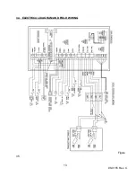
Страница 18: ...13 98 0155 Rev C 3 4 ELECTRICAL DIAGRAM AND FIELD WIRING Figure 3 5 ...
Страница 19: ...14 98 0155 Rev C Fig Figure 3 6 ...
Страница 20: ...15 98 0155 Rev C Figure 3 7 ...
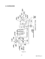
Страница 21: ...16 98 0155 Rev C 3 5 FLOW DIAGRAMS Figure 3 8 ...
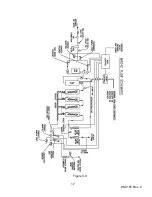
Страница 22: ...17 98 0155 Rev C Figure 3 9 ...
Страница 23: ...18 98 0155 Rev C Figure 3 10 ...
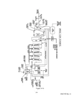
Страница 24: ...19 98 0155 Rev C Figure 3 11 ...
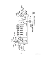
Страница 25: ...20 98 0155 Rev C Figure 3 12 ...
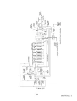
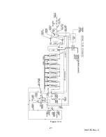
Страница 26: ...21 98 0155 Rev C Figure 3 13 ...
Страница 45: ...40 98 0155 Rev C FIGURE 6 2 Feed Water Adjustment Potentiometer Product Water Adjustment Potentiometer ...
Страница 46: ...41 98 0155 Rev C FIGURE 6 3 ...


