


37
98-0155 Rev. C
CONDUCTIVITY
The Conductivity is shown on the top line after the unit operating status. When the unit is in
STANDBY, because of a shutdown condition, the reading is replaced with ‘----’. If the reading
is over range, the reading is shown as ‘^^^^’ when in the OPERATE mode.
OPERATING HOURS
The current operating hours are shown on the bottom line.
TEMPERATURE
The current water temperature is shown on the bottom line to the right of operating hours.
When the unit is in STANDBY due to a shutdown condition, the reading is replaced with ‘---‘.
WARNING MESSAGES
Warning messages are also shown on the second line. If any warnings are active, the active
warnings will alternate with the normal displays for the bottom line. The following lists the
warning messages.
HI COND - The Conductivity reading has exceeded the programmed limit.
TANK FULL OPERATION
The unit can be operated with 1 or 2 level switches. With 1 level switch, the switch is
connected to the tank full high input. When this switch has been active for 5 seconds, the unit
will shut down on tank full. TANK FULL will show on the display. When the tank full condition
clears, the display will show TANK FULL 99. The number is the tank full restart time and the
unit will restart when this delay times out.
For 2 level switch operation, the upper switch is connected to the tank full high input and the
lower switch is connected to the tank full low input. When both switches are “open”, the
MROZ unit will start. The MROZ unit will continue to run when the water level rises, and while
the lower switch becomes active (closed). When the upper switch becomes active (closes),
after the 5 second delay, the MROZ unit will shut down. TANK FULL will show on the display.
When the tank level drops and the upper level switch clears, the display will show TANK
FULL 99 and the MROZ unit will remain off. The number is the tank full restart time and the
number will blink until the lower level switch clears (opens). When the lower level switch
clears (opens), the number will remain steady and the MROZ will restart when the delay times
out.
Содержание MRO3Z
Страница 2: ...98 0155 Rev C ...
Страница 5: ...98 0155 Rev C ...
Страница 13: ...8 98 0155 Rev C MRO7Z and MRO8Z CONFIGURATION SHOWN BELOW Figure 3 2 ...
Страница 15: ...10 98 0155 Rev C 3 2 INTERNAL CABINET TOP AND SIDE VIEW Figure 3 3 ...
Страница 16: ...11 98 0155 Rev C 3 3 INTERNAL CABINET TOP AND SIDE VIEW CONT Figure 3 4 ...
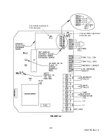
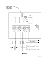
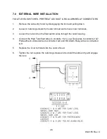
Страница 18: ...13 98 0155 Rev C 3 4 ELECTRICAL DIAGRAM AND FIELD WIRING Figure 3 5 ...
Страница 19: ...14 98 0155 Rev C Fig Figure 3 6 ...
Страница 20: ...15 98 0155 Rev C Figure 3 7 ...
Страница 21: ...16 98 0155 Rev C 3 5 FLOW DIAGRAMS Figure 3 8 ...
Страница 22: ...17 98 0155 Rev C Figure 3 9 ...
Страница 23: ...18 98 0155 Rev C Figure 3 10 ...
Страница 24: ...19 98 0155 Rev C Figure 3 11 ...
Страница 25: ...20 98 0155 Rev C Figure 3 12 ...
Страница 26: ...21 98 0155 Rev C Figure 3 13 ...
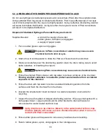
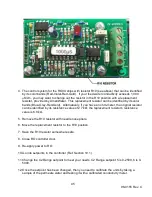
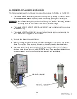
Страница 45: ...40 98 0155 Rev C FIGURE 6 2 Feed Water Adjustment Potentiometer Product Water Adjustment Potentiometer ...
Страница 46: ...41 98 0155 Rev C FIGURE 6 3 ...