


57
98-0155 Rev. C
9.3 PUMP REPAIR
The following procedures are instructions for removing the pump from the unit.
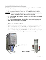
The MRO3Z-MRO6Z Series has a pump with a ¾ NPT throttle valve.
The MRO7Z-MRO8Z Series has a pump with a 1 NPT throttle valve.
Before replacing the pump, be sure the pump’s thermal overload has not tripped.
Allow the pump to sit at least 5 minutes to allow it to reset, then try to re-start the pump.
1. Turn off the water supply and the power supply to the MROZ. Unplug the power cord
from the electrical outlet and turn off the wall disconnect for the high voltage. Make
sure there is a “lockout” placed on the handle of the wall disconnect.
2. Open the front panel of the cabinet. Disconnect the pump from the control box by
disconnecting the wires from the connectors located in the control box (See controller
drawings in Section 6 ).
3. Remove the 1/2 black plastic conduit from the wires. Cut the wire harness half way to
the pump. Keep the half of the wire harness that way connected to the motor starter in
the RO3X cabinet for future use.
4. Disconnect the suction and recirculation headers from pump by loosening the unions
coming out of the suction and discharge of the pump. Remove hose and fittings from
top of pump going to first membrane inlet.
5. Remove the clamps securing the pump assembly and remove the assembly from the
frame.
6. Pull locking ring on top of housing, slide pump out of the housing and remove pump
cap and fittings from pump.
7. Package pump for shipping to Ameriwater (If still under warranty).
9.4 INSTALLING A REPLACEMENT PUMP ASSEMBLY
The following procedures are instructions to install the replacement pump assembly.
1. Compare the new pump to the existing to ensure that the voltage is correct.
2. Slide together pump end and pump motor, tightening nuts in a cross pattern
3. Tighten nuts to between 90-120 in.-lbs.
4. Run wires through sealcon fitting on pump cap.
5. Mount wire shroud with care as to not scuff, crimp or cut wires.
6. Tighten sealcon around wires.
7. Slide the new pump assembly into the housing taking care that the o-ring does not roll.
Содержание MRO3Z
Страница 2: ...98 0155 Rev C ...
Страница 5: ...98 0155 Rev C ...
Страница 13: ...8 98 0155 Rev C MRO7Z and MRO8Z CONFIGURATION SHOWN BELOW Figure 3 2 ...
Страница 15: ...10 98 0155 Rev C 3 2 INTERNAL CABINET TOP AND SIDE VIEW Figure 3 3 ...
Страница 16: ...11 98 0155 Rev C 3 3 INTERNAL CABINET TOP AND SIDE VIEW CONT Figure 3 4 ...
Страница 18: ...13 98 0155 Rev C 3 4 ELECTRICAL DIAGRAM AND FIELD WIRING Figure 3 5 ...
Страница 19: ...14 98 0155 Rev C Fig Figure 3 6 ...
Страница 20: ...15 98 0155 Rev C Figure 3 7 ...
Страница 21: ...16 98 0155 Rev C 3 5 FLOW DIAGRAMS Figure 3 8 ...
Страница 22: ...17 98 0155 Rev C Figure 3 9 ...
Страница 23: ...18 98 0155 Rev C Figure 3 10 ...
Страница 24: ...19 98 0155 Rev C Figure 3 11 ...
Страница 25: ...20 98 0155 Rev C Figure 3 12 ...
Страница 26: ...21 98 0155 Rev C Figure 3 13 ...
Страница 45: ...40 98 0155 Rev C FIGURE 6 2 Feed Water Adjustment Potentiometer Product Water Adjustment Potentiometer ...
Страница 46: ...41 98 0155 Rev C FIGURE 6 3 ...