44
98-0155 Rev. C
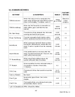
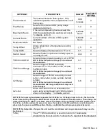
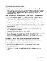
6.5 TO DISPLAY OR CHANGE SETPOINTS
NOTE: Please contact your AmeriWater representative prior to changing set points.
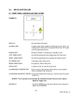
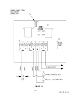
1. Refer to Figure 6.1 for the location of the keys used to display or change the Setpoints and
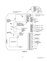
Figure 6.2 for the location of the write protect jumper, J3. For the unit to be able to accept
a change in a Setpoint, the shorting jumper must be in the WRITE PROTECT OFF
position (center and left pins).
NOTE: Setpoints cannot be changed if the write protect jumper is in the ON position.
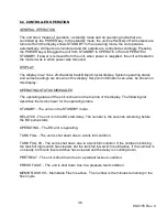
2. Use the LEFT and RIGHT ARROW keys to display the Setpoints. Each press of an arrow
key will advance the display to the next Setpoint. The Left arrow key starts with the
beginning Setpoint and the Right arrow key starts with the last Setpoint.
3. The Up and Down arrow keys are used to increase or decrease the Setpoint value. The
value will change by 1 count each time a key is pressed. If the key is pressed and held for
>1 second, the Setpoint value will change at a fast rate. When the key is released, the fast
rate will be reset. Pressing both the UP and DOWN ARROW keys together will reset the
set point value to 0.
4. Pressing the ALARM SILENCE/RESET key at any time will cancel the operation and
return the display to the main screen.
5. To accept the new set point value, press the ENTER key.
6. The unit will beep twice if the change is accepted. If the write protect jumper is on, the unit
will show WRITE PROTECTED on the display and one long beep will sound.
7. When finished changing Setpoints, the write protect jumper should be placed in the ON
position (center and right pins).
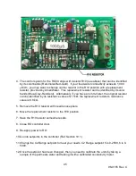
6.6 CHANGING RESISTORS ON THE RO CONTROL BOARD FOR C2 RANGE
If your incoming feed conductivity is above the Factory setting C2 range of 0-1000 micro-
seimens, then you’ll have to swap the resistors on the conductivity board.
1. Switch off the RO by pressing the POWER key (the display will show STANDBY).
2. Turn off all power to RO.
3. Open door on RO controller. Conductivity board you need to get to is on the back of
the door.
Содержание MRO3Z
Страница 2: ...98 0155 Rev C ...
Страница 5: ...98 0155 Rev C ...
Страница 13: ...8 98 0155 Rev C MRO7Z and MRO8Z CONFIGURATION SHOWN BELOW Figure 3 2 ...
Страница 15: ...10 98 0155 Rev C 3 2 INTERNAL CABINET TOP AND SIDE VIEW Figure 3 3 ...
Страница 16: ...11 98 0155 Rev C 3 3 INTERNAL CABINET TOP AND SIDE VIEW CONT Figure 3 4 ...
Страница 18: ...13 98 0155 Rev C 3 4 ELECTRICAL DIAGRAM AND FIELD WIRING Figure 3 5 ...
Страница 19: ...14 98 0155 Rev C Fig Figure 3 6 ...
Страница 20: ...15 98 0155 Rev C Figure 3 7 ...
Страница 21: ...16 98 0155 Rev C 3 5 FLOW DIAGRAMS Figure 3 8 ...
Страница 22: ...17 98 0155 Rev C Figure 3 9 ...
Страница 23: ...18 98 0155 Rev C Figure 3 10 ...
Страница 24: ...19 98 0155 Rev C Figure 3 11 ...
Страница 25: ...20 98 0155 Rev C Figure 3 12 ...
Страница 26: ...21 98 0155 Rev C Figure 3 13 ...
Страница 45: ...40 98 0155 Rev C FIGURE 6 2 Feed Water Adjustment Potentiometer Product Water Adjustment Potentiometer ...
Страница 46: ...41 98 0155 Rev C FIGURE 6 3 ...

