


10
13
If your System Type is:
• Gas Furnace - Single Stage, Perform System Checkout step 16
• Gas Furnace - Multistage, perform step 14 then step 14A
• Electric Furnace, perform step 14 then step 14B
• Heat Pump, perform step 14 then step 14C
• Heat Pump Dual Fuel, perform step 14 then step 14D
12
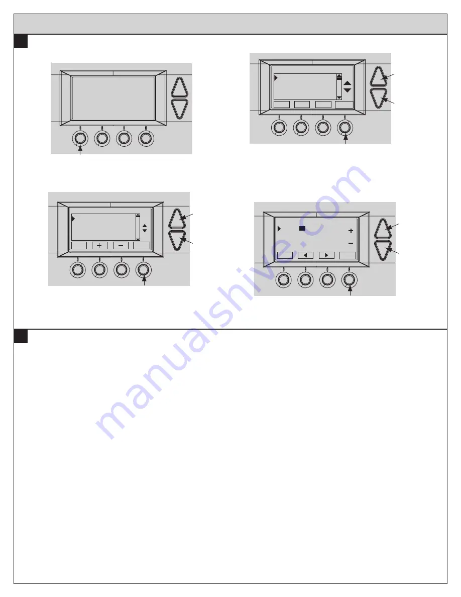
Set Time and Date
a. Press the
Menu button twice.
MENU button
MENU MODE FAN RUN
75
76 H
74 C
11:15 AM
b. Scroll up or down to
User Settings (it is the first option),
then press the
Select button.
c. Scroll up or down to
Set Clock (it is the first option), then
press the
Select button.
Done
Select
User Settings
Set Clock
Filter Service
Maint Service
Screen Timeout
Select button
Scroll
up
Scroll
down
d. Press
or
to highlight the data you want to change.
e. Scroll up or down (
+ or -) to make changes.
f.
Press the
Set button when you are finished.
g. Press the
Done button twice to exit the menu.
Set button
Scroll
up
Scroll
down
Back
Set Clock
Set
Time
10
:15 AM
Date 3 / 23 / 09
Day Mon
System Settings at Thermostat
Set button
Scroll
up
Scroll
down
Done
Set Clock
Set
User Settings
Usage Graph
ESM Setpoints
Z-Wave Install


