Chapter 3 AMIBIOS and WINBIOS
32
Step 7 Connect Cables
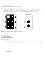
When connecting chassis connectors to the motherboard, make sure to connect the correct connector end. Most connector wires are color-
coded. Match the color of the wires leaving the switch or LED to the same pin on the connector end. There may be more than one
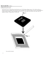
connector with the same color-coded wires. If so, follow the wire to the switch or LED. Pin 1 of all connectors is indicated on the
motherboard by a pointed box around the connector. Pin 1 is always at the pointed end of the box, as shown below:
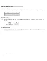
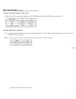
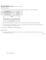
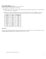
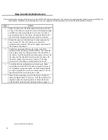
Connect the following cables to the following jumpers on the motherboard:
• Reset switch cable to J46,
• Speaker cable to J40,
• external battery connector to J18,
• Keyboard lock cable to J41,
• Turbo LED cable to J54, and
• IDE Activity Indicator LED cable to J47.
J46 Reset Switch Connector
J46 is a two-pin single-inline berg that is attached via a cable to an externally-mounted reset switch. When the reset switch is pressed, the
system performs a hard reset. Pin 1 is ground and Pin 2 is Hard Reset.
Cont'd
Содержание Super Voyager PCI-II
Страница 1: ...American Megatrends Inc Super Voyager PCI II 486 ISA Motherboard User s Guide MAN 724 4 21 95...
Страница 12: ...Super Voyager PCI II 486 ISA Motherboard User s Guide 9 2 Installation...
Страница 14: ...Super Voyager PCI II 486 ISA Motherboard User s Guide 11 Motherboard Layout...
Страница 59: ...56...
Страница 61: ...Chapter 4 Flash Programming 58...
Страница 63: ...Appendix A Upgrading Cache Memory 60...

