background image

Interrupters User Guide

Chapter 5: Interrupter Programming

37

Figure 5-2.   Output Parameters Screen         

 3. 

To move from one field to another, press 

 or 

 until the cursor is positioned on the field 

you want to change.         

 4. 

To change the field, press 

 until the desired output parameter displays in the selected field.         

 5. 

Press 

ENTER

 to save the setting or 

PREV

 to return to the Options menu.         

Setting the UTC Offset

The UTC (Universal Time) can be set from UTC –12 to UTC +12. The following table lists examples of 
typical time zones with corresponding UTC. The procedure following the table explains how to 
configure the interrupter with a UTC of your choice.     

Time Zone             

UTC             

Eastern Standard Time             

–05             

Central Standard Time             

–06             

Mountain Standard Time             

–07             

Pacific Standard Time             

–08             

Eastern Daylight Time             

–04             

Central Daylight Time             

–05             

Mountain Daylight Time             

–06             

Pacific Daylight Time             

–07             

Table 5-1.  Time Zone and UTC Examples       

Complete the following steps to set the UTC:     

 1. 

From the main menu, press 

4

 on the keypad to display the Options menu.         

Figure 5-1.   Options Menu         

 2. 

Press 

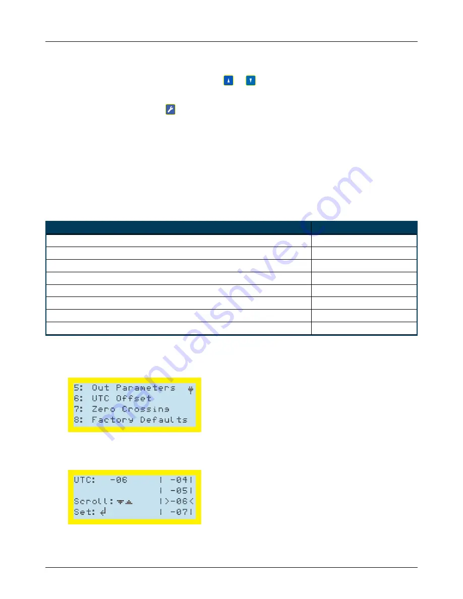
6

 to display the UTC Offset screen:         

Содержание MicroMax GPS360

Страница 1: ...Proven compliance solutions Relentless service Interrupters User Guide Interrupters User Guide...

Страница 2: ...ithout the written permission of American Innovations is strictly forbidden The American Innovations logo and icon and products are trademarks of American Innovations Ltd Other trademarks and trade na...

Страница 3: ...ay 9 Connecting the GPS Antenna 11 Setting Display Contrast 12 Viewing GPS Info 12 Running a Test Program 13 Chapter 3 GPS350 Installation 14 Installing the GPS350 Interrupter 14 Determining a Power S...

Страница 4: ...ting Bullhorn Tools 40 Configuring the Interrupter 41 Viewing Unit Information 42 Using Saved Templates 42 Setting Up Interruption Options 43 Setting Up Interruption Programs 44 Setting Up an Interfer...

Страница 5: ...Interrupters User Guide v Appendix E Regulatory Notices 63 Export Control Classification Number 63...

Страница 6: ...GPS300 GPS350 and GPS360 interrupters are fully programmable satellite synchronized interrupters that are capable of interrupting rectifier bond or any other current Cycles can be programmed using any...

Страница 7: ...in use rectifier on and no interruption Relay and Interruption Features The GPS300 GPS350 and GPS360 interrupters can be connected to almost any external current relay or multiple relays using a 12V c...

Страница 8: ...econds in 0 1 second increments l Synchronization triggering accuracy is within 1 s with any other GPS300or GPS350 interrupter and collectively is less than 5 s after the PPS signal precise positionin...

Страница 9: ...ore the next OFF cycle on the interrupter connect the banana plugs on the JR 2 adapter cable to the INPUT connections on the power relay assembly cable Wait until an OFF cycle has executed The power c...

Страница 10: ...1 1 Power Cable and AC DC Power Input Cable with Alligator Clips l GPS Antenna The GPS antenna should be mounted on a metal surface with a clear view of the sky Figure 1 2 GPS Antenna Below is an exa...

Страница 11: ...Voltmeter l Hand tools for installing relay Optional Hardware and Software MicroMax GPS300 GPS350 and GPS360 interrupters can be programmed through the unit s keyboard refer to Configuring with Unit K...

Страница 12: ...l Adobe Reader version 6 0 or higher available from the Adobe website Refer to Configuring with Bullhorn Tools on page 39 for details on configuring with this software Contacting Technical Services A...

Страница 13: ...nstalling the GPS300 Interrupter When completing the following procedure refer to Supplied Power Cables and GPS Antenna on page 4 for input and output voltage specifications WARNING Make sure to follo...

Страница 14: ...ay The GPS300 requires an external relay to perform interruptions The GPS300 can be used with an AC DC or mercury relay Refer to Mercury Relay Advisory on page 61 if working with a mercury relay 1 Tur...

Страница 15: ...wer Cable Connections 5 Connect the AC DC Power Input cable to the power cable s INPUT connection Figure 2 3 AC DC Power Input Cable Connected to Twisted Wire Cable 6 Clip the AC DC Power Input cable...

Страница 16: ...s completes the interrupter displays the main menu If the main menu does not display this may take several minutes make sure the interrupter is not currently running another program If another program...

Страница 17: ...time is shown in military time 24 hours and uses the HH MM SS format to represent hours minutes and seconds The date is shown in MM DD YYYY format to represent the month day and year The plug symbol i...

Страница 18: ...r when the test is done Figure 2 1 Test Mode The following list describes the type of information shown on the Test Mode screen and that is used for the test l TEST MODE ON OFF DONE The cycle that the...

Страница 19: ...on page 18 l Running a Test Program on page 19 Installing the GPS350 Interrupter When completing the following procedure refer to Technical Specifications on page 57 for input and output voltage spec...

Страница 20: ...42 V AC or 10 60 V DC 2 A 120 V AC convenience outlet to use with the 12 V DC wall adapter 3 A DC source such as a 10 60 V DC battery Figure 3 1 Power Source Options Connecting the Built in Relay to a...

Страница 21: ...me tap settings that were connected by the change bar 4 If interrupting the DC power a Disconnect DC output cable b Connect one of the interrupter s relay cables to the output c Slide shrink wrap tube...

Страница 22: ...rmation briefly appears in the display 3 After the initialization process completes the interrupter displays the main menu If the main menu does not display make sure the interrupter is not currently...

Страница 23: ...ormation for the current number of satellites in view time zone antenna and the current time and date With the main menu displaying press 2 to display the GPS Info screen Press PREV to return to the m...

Страница 24: ...n as the internal GPS locates satellites For synchronized interruption or interference make sure the antenna position enables at least a 2D lock Running a Test Program Before programming the interrupt...

Страница 25: ...Interrupters User Guide Chapter 3 GPS350 Installation 20 Cycle setting in Out Parameters refer to Output Parameters on page 36 l CYCLE 1s ON 5s OFF The timing of the on and off cycle...

Страница 26: ...ion process includes the following steps l Installing the GPS360 Interrupter on page 21 l Setting Display Contrast on page 27 l Viewing GPS Info on page 28 l Running a Test Program on page 29 Installi...

Страница 27: ...e features You can bypass the GPS screen by pressing PREV 3 The unit will turn off the LCD screen power save mode 30 seconds after the last key press If an interruption program was not selected to run...

Страница 28: ...le connected to a computer Figure 4 1 Power Source Options NOTE If available use line power to power the GPS360 to save the internal battery power Connecting the Built in Relay to a Rectifier The GPS3...

Страница 29: ...the DC power a Disconnect DC output cable b Connect one of the interrupter s relay cables to the output c Slide shrink wrap tube on to the other relay cable d Connect the DC output cable to the interr...

Страница 30: ...s the main menu If the main menu does not display make sure the interrupter is not currently running another program If another program is running press PREV and then ENTER The main menu displays avai...

Страница 31: ...the internal one If you are going to use an external relay the GPS360 must be connected to line power such as to the rectifier 1 Connect the power cable to the interrupter Line up the notch on the po...

Страница 32: ...Connected to Rectifier Taps NOTE If you are connecting to a DC power source such as a battery the power requirement is 10 60 V DC Setting Display Contrast Use the up and down arrow keys on the keypad...

Страница 33: ...ected or loose the status message Antenna OPEN displays If the antenna is shorted the status message Shorted displays l 3D Fix SV 07 07 Shows whether a 2D or 3D GPS lock has been obtained and the numb...

Страница 34: ...MODE ON OFF DONE The cycle that the interruption is running during the test The test runs through an off and on sequence for a few seconds It will then display DONE when it completes the test The plu...

Страница 35: ...ullhorn Tools to configure the interruption and interference programs Status Icons Table 1 1 defines the status icons shown on the MicroMax GPS300 GPS350 and GPS360 interrupters displays Icon Descript...

Страница 36: ...battery for interruption Table 5 1 Status Icons cont d Configuring with Unit Keypad The MicroMax interrupters can be programmed through keypad menus and buttons The following set up tasks can be done...

Страница 37: ...ved program The first line also shows the On and Off times of the interruption cycle l Start 06 00 01 01 14 The interruption schedule Start Stop and the start time and date For Daily this line would a...

Страница 38: ...o confirm If ENTER is not pressed within a few seconds the interrupter returns to the interruption program NOTE If the interrupter is powered off or loses power while executing an interruption program...

Страница 39: ...the ENTER key to move to next screen 2 To move from one field to another press or 3 Enter new values as necessary using the keypad 4 Press ENTER to move to the Interruption Program Setup screen 5 Set...

Страница 40: ...begins again Figure 5 6 Interference Program Screen 3 7 To cancel the program press PREV A cancellation confirmation screen displays Figure 5 7 Cancellation Confirmation Screen 8 Press ENTER to cancel...

Страница 41: ...actory Defaults with Keypad on page 38 Output Parameters Output parameters are set to accommodate various current switch configurations and enable synchronization with other interrupters Switch can be...

Страница 42: ...UTC 12 to UTC 12 The following table lists examples of typical time zones with corresponding UTC The procedure following the table explains how to configure the interrupter with a UTC of your choice T...

Страница 43: ...keypad to display the Options menu Figure 5 1 Options Menu 2 Press 7 to display the Zero Crossing Switching screen Figure 5 2 Zero Crossing Switching Screen 3 Press to change the status of Zero Crossi...

Страница 44: ...settings that are different than the defaults After resetting the interrupter the Options menu displays again Press PREV to return to the main menu Configuring with Bullhorn Tools Bullhorn Tools is th...

Страница 45: ...r it was installed on with an Internet connection You will not need to uninstall a previous version and then download a new version and install it 3 If Bullhorn Tools does not launch automatically cli...

Страница 46: ...overwritten by the applied template l Setting Up Interruption Options set interruption options such as UTC Offset Output Mode Sync Mode and Zero Crossing l Setting Up Interruption Programs create up t...

Страница 47: ...tings and Power panes as well as separate panes for each Program Figure 5 1 Bullhorn Tools Device Overview Window 2 Click Refresh to read unit settings and verify the unit and Bullhorn Toolssoftware a...

Страница 48: ...lying a Saved Template on page 51 complete these steps if a saved template is currently available to use from Bullhorn Tools Setting Up Interruption Options Interruption options such as UTC Offset Out...

Страница 49: ...onization select either On Off or Off On from the Sync Mode drop down list 3 The MicroMax interrupters usually use a GPS reading to take timed measurements Zero Crossing allows you to use the instant...

Страница 50: ...chedule such as Daily Start Stop or Continuous from the Interrupter Mode drop down list 3 If you selected Daily Figure 5 2 Daily Settings a Enter a start time in Start Time field The time defaults to...

Страница 51: ...ime field Use the up and down arrows in the field to increase decrease time by 0 1 seconds 4 If you selected Start Stop Figure 5 3 Start Stop Settings a Enter a start date in the Start Date field in t...

Страница 52: ...arrows in the field to increase decrease time by 0 1 seconds 5 If you selected Continuous Figure 5 5 Continuous Settings a Enter a value in seconds in the On Time field Use the up and down arrows in t...

Страница 53: ...ease time by 0 1 seconds 4 Enter a value in seconds in the Off Time field Use the up and down arrows tin the field to increase decrease time by 0 1 seconds 5 Select Enabled from the Interference Mode...

Страница 54: ...If a template is available for the unit type you plan to configure you can apply the template to the current unit You can also import a saved template to Bullhorn Tools and then apply it to the curre...

Страница 55: ...ement Figure 5 1 Template Management 2 Click Import to search for a saved template on your computer 3 Navigate to the template and click Open The template now displays in the Select template list and...

Страница 56: ...re 5 1 Load Template 2 From the Apply Template window select a template that has been previously saved in Bullhorn Tools from the list shown in the Select template drop down menu Figure 5 2 Select Tem...

Страница 57: ...he settings are applied to the unit Exporting or Deleting Saved Templates Saved templates can be exported to your computer or deleted from Bullhorn Tools Complete the following steps to either export...

Страница 58: ...ctory defaults all current settings will be replaced with these default settings Refer to Factory Defaults Settings on page 56 for a list of these settings The unit can also be reset to factory defaul...

Страница 59: ...ing the steps in this section Contact Technical Services techservices aiworldwide com for additional assistance 1 Click Action Upgrade Firmware Figure 5 1 Upgrade Firmware 2 Click Browse to search for...

Страница 60: ...Interrupters User Guide Chapter 5 Interrupter Programming 55 The configuration is now complete...

Страница 61: ...Defaults with Bullhorn Tools on page 53 Setting Value Interruption 9 programs Continuous on off times in seconds Program 1 3 0 1 0 Program 2 0 8 0 2 Program 3 3 0 1 0 Program 4 4 0 1 0 Program 5 12 0...

Страница 62: ...to 70 C LCD visible from 20 C to 60 C Programmable schedules 9 programmable schedules start phase on off 9 programmable schedules start phase on off 9 programmable schedules start phase on off Display...

Страница 63: ...0 A 60 A and 100 A AC Solid State Normally Closed NC 80 A and 100 A DC Solid State Normally Closed NC 100 A Can be used with external relays Can be used with external relays Integrated battery N A N A...

Страница 64: ...59 l GPS360 Derating Table on page 59 GPS350 Derating Table Before setting up the GPS350 interrupter consider the outside temperatures both high and low that the interrupter will be exposed to for the...

Страница 65: ...5 Table C 1 GPS360 Derating Table For Setup 1 the GPS360 can be in any orientation with the mounting magnets attached for easy installation For Setup 2 the GPS360 mounting magnets have been removed an...

Страница 66: ...manufacturer s documentation to select the appropriate relay for the application Durakool information can be found on the AEC web page at the following address http www aecsensors com html In the Dura...

Страница 67: ...e utilized in this manner AI adds a serial number to relays that is supplied that we supply to enable the tracking of the shipment date The approximate age of the relay may be used to assist AI in ret...

Страница 68: ...erence will not occur in a particular installation If this equipment does cause harmful interference to radio or television reception which can be determined by turning the equipment off and on the us...

Отзывы: