77
HELIX™ Manual
(P/N 26291)
Chapter 4: System Installation
Rev A (February 2018)
HELIX™ PCU
Fire Suppression System
4.
10
STRIKE
Control Unit Programming
Following the complete installation of all components and termination of all field wiring, the Amerex
STRIKE ECS may be programmed to match utilized circuits or customized as desired.
Do NOT
connect the supplied batteries to the
STRIKE
Control Unit until directed to do so in Section
4.12.2.
The STRIKE Control Unit is pre
-
programmed with the following circuits enabled, requiring
that these circuits be used and connected to the STRIKE Control Unit:
•
Single Detection Zone (Zone #1)
•
Single Actuation Zone (Zone #1)
•
Manual Pull Circuit
•
Pressure Switch Circuit (Jumper wire installed on STRIKE Control Unit, TB1).
•
If additional circuits are needed and connected, programming is required. The default settings
and all available programming options are also shown in Table 4.10.3. A trained technician may
program a system for any desired configuration as detailed in the following sections.
The STRIKE Control Unit is provided with two installed, but unconnected batteries. However,
because programming functions consume power, an additional spare Replacement Battery (P/N
24903) is needed to provide temporary power to accomplish all programming functions so that
power is not drained from the included service batteries. This temporary battery must also be used
during function testing and initial commissioning (See Section 4.11). Also, programming functions
require use of the PC Interface Cable (P/N 16609) and a laptop or tablet with the latest Amerex
STRIKE PC software installed. The latest version of PC software is available on and can be
downloaded from the www.amerex
-
fire.biz website.
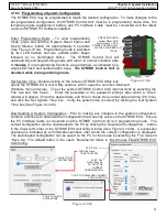
4.10.1 Temporary Power Supply Connection
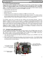
The spare Replacement Battery (P/N 24903) connects directly to the STRIKE Control Unit at the
‘Primary’ battery input connection. The secondary battery (included with the STRIKE Control Unit) is
also needed in order to avoid a resulting ‘Battery Fault’ condition on the STRIKE Control Unit.
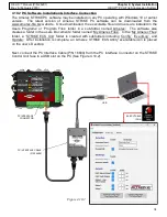
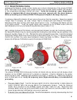
Connect these batteries in the following order (See Figure 4.10.1):
1.
First, insert the spare Replacement Battery (P/N 24903) connector into the STRIKE Control Unit
at the ‘Primary’ location.
2.
Next, connect the provided Secondary battery at the ‘Secondary’ location. The STRIKE Control
Unit will then power up, illuminate, and indicate system status. The green ‘System Normal’ LED
will indicate fully connected batteries.
1. FIRST, CONNECT SPARE
REPLACEMENT BATTERY (P/N
24903) IN ‘Primary’ LOCATION ON
STRIKE CONTROL
UNIT
2. THEN, CONNECT INCLUDED
SECONDARY BATTERY IN
‘Secondary’ LOCATION
ON STRIKE
CONTROL UNIT
INCLUDED PRIMARY BATTERY
DO NOT CONNECT
IN
C
LU
D
E
D
S
E
CO
NDA
RY
B
A
T
T
E
R
Y
Figure 4.10.1
SPARE REPLACEMENT
BATTERY (P/N 24903)


