84
HELIX™ Manual
(P/N 26291)
Chapter 4: System Installation
Rev A (February 2018)
HELIX™ PCU
Fire Suppression System
4.11 Function Testing & Initial Commissioning
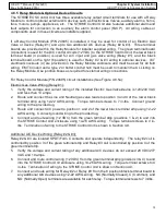
After the desired configuration has been uploaded from a PC, the Amerex STRIKE ECS and
components must be functionally tested as part of the initial commissioning, just prior to placing the
system into service. These tests include STRIKE Control Unit display, manual pull, actuation
circuits, detection sensor, and circuit fault testing as shown in the following steps. Any desired
output circuits to Relay Modules and all associated wiring must be installed and connected to the
STRIKE Control Unit.
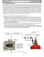
Do NOT connect the supplied batteries to the
STRIKE
Control Unit until
directed to do so later in this section.
Because function testing consumes power, a temporary
Spare Replacement Battery (P/N 24903) is needed to accomplish all testing functions. If not already
installed from programming per Section 4.10, install the temporary spare Replacement Battery as
described in Section 4.10.1.
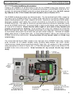
Function testing includes activating the actuation circuits, and therefore all Linear Actuators
must be disconnected from each actuation circuit in order to prevent Linear Actuator
consumption or an unwanted discharge of the Amerex HELIX Fire Suppression System. A
Fire Alarm Module (P/N 23651) must be installed in place of each Linear Actuator on the
actuation circuits.
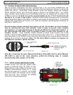
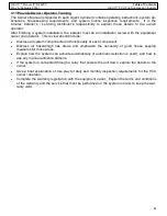
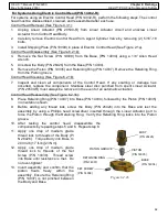
These resettable modules simulate an actual Linear Actuator and visually
indicate a fully functioning actuation circuit during testing (See Figure 4.11). A fault condition will
occur temporarily on the STRIKE Control Unit when disconnecting any Linear Actuators until Alarm
Modules are connected in their place.
Note: The Fire Alarm Module contains and requires a 9
volt battery for operation, replace if needed.
Figure 4.11
FIRE ALARM MODULE
(P/N 23651)
CONNECT TO ACTUATION
LEAD CABLE (P/N 24411
-
XX)
IN PLACE OF LINEAR
ACTUATOR
VISUAL LED INDICATOR
COLOR CODED YELLOW
Only after connecting the spare Replacement Battery (P/N 24903) and Fire Alarm Modules
(P/N 23651) in place of ALL Linear Actuators, perform the following steps to complete
function testing of the Amerex
STRIKE
ECS
.
4
.11.1
STRIKE
Control Unit Display Testing
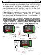
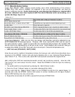
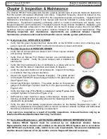
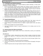
STRIKE Control Unit LED and audible alarm
testing is performed using the ‘Push to Test’
button (Amerex Logo) located on the face of the
STRIKE Control Unit (See Figure 4.11.1). Press
and hold the button for 3 seconds. All STRIKE
Control Unit LEDs will illuminate and the audible
alarm will beep once, indicating the STRIKE
Control Unit is functioning properly.
Figure 4.11.1
PRESS AND
HOLD THE
AMEREX LOGO
BUTTON FOR 3
SECONDS

