background image

Introduction

BreezeMAX Wi² and BreezeACCESS Wi² System Manual

221

To reset the AP to factory defaults and 

FORCE it back into its default controlled mode

, follow 

this procedure:

1

Select 

Maintenance > System

.

2

Under 

Factory reset

, click 

Reset to Factory Default

.

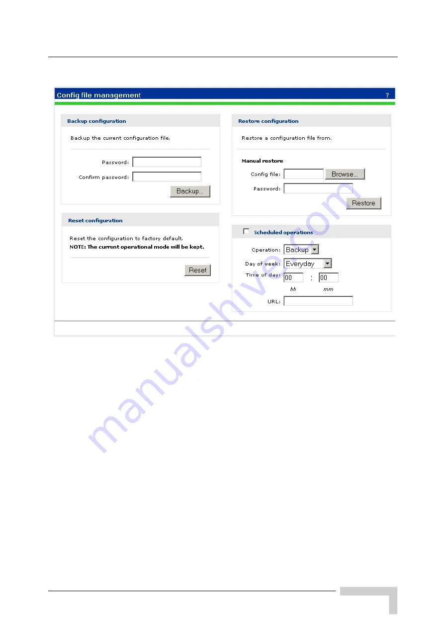
Figure B-1: Config File Management

Содержание BreezeACCESS Wi2

Страница 1: ...BreezeMAX Wi and BreezeACCESS Wi System Manual SW Version 5 2 June 2008 P N 215017 ...

Страница 2: ...ii BreezeMAX Wi and BreezeACCESS Wi System Manual Document History Document History Topic Description Date Issued This is the document s first Release March 2007 ...

Страница 3: ...ble for errors contained herein or for incidental or consequential damages in connection with the furnishing performance or use of this manual or equipment supplied with it Warranties and Disclaimers All Alvarion Ltd Alvarion products purchased from Alvarion or through any of Alvarion s authorized resellers are subject to the following warranty and product liability terms and conditions Exclusive ...

Страница 4: ...RED OR INTENDED FOR USE OR RESALE IN APPLICATIONS WHERE THE FAILURE MALFUNCTION OR INACCURACY OF PRODUCTS CARRIES A RISK OF DEATH OR BODILY INJURY OR SEVERE PHYSICAL OR ENVIRONMENTAL DAMAGE HIGH RISK ACTIVITIES HIGH RISK ACTIVITIES MAY INCLUDE BUT ARE NOT LIMITED TO USE AS PART OF ON LINE CONTROL SYSTEMS IN HAZARDOUS ENVIRONMENTS REQUIRING FAIL SAFE PERFORMANCE SUCH AS IN THE OPERATION OF NUCLEAR ...

Страница 5: ...ENTAL PUNITIVE OR CONSEQUENTIAL DAMAGES OF ANY KIND WHETHER ARISING UNDER BREACH OF CONTRACT TORT INCLUDING NEGLIGENCE STRICT LIABILITY OR OTHERWISE AND WHETHER BASED ON THIS AGREEMENT OR OTHERWISE EVEN IF ADVISED OF THE POSSIBILITY OF SUCH DAMAGES b TO THE EXTENT PERMITTED BY APPLICABLE LAW IN NO EVENT SHALL THE LIABILITY FOR DAMAGES HEREUNDER OF ALVARION OR ITS EMPLOYEES OR AGENTS EXCEED THE PUR...

Страница 6: ...on and national codes it is highly recommended to ensure that the outdoor unit and the antenna mast when using external antenna are grounded and suitable lightning protection devices are used so as to provide protection against voltage surges and static charges In any event Alvarion is not liable for any injury damage or regulation violations associated with or caused by installation grounding or ...

Страница 7: ...otherwise noted Alvarion Ltd reserves the right to alter the equipment specifications and descriptions in this publication without prior notice No part of this publication shall be deemed to be part of any contract or warranty unless specifically incorporated by reference into such contract or warranty The information contained herein is merely descriptive in nature and does not constitute an offe...

Страница 8: ...vi BreezeMAX Wi and BreezeACCESS Wi System Manual Legal Rights ...

Страница 9: ...r is encouraged to try to correct the interference by one of the following measures Reorient or relocate the receiving antenna Increase the separation between the equipment and receiver Connect the equipment into an outlet on a circuit different from that to which the receiver is connected Consult the dealer or an experienced radio TV technician for help FCC Caution Any changes or modifications no...

Страница 10: ...outdoor operation license requirements and allowed channels of operation apply in some countries as described below This device requires that the user or installer properly enter the current country of operation in the command line interface as described in the user guide before operating this device This device will automatically limit the allowable channels determined by the current country of o...

Страница 11: ...ACCESS Wi System Manual ix About This Manual º In Belgium outdoor operation is only permitted using the 2 46 2 4835 GHz band Channel 13 º In France outdoor operation is only permitted using the 2 4 2 454 GHz band Channels 1 7 ...

Страница 12: ......

Страница 13: ...s how to initially configure the APs in autonomous mode and establish a connection through the AP to the Internet Chapter 4 Working with virtual networks Describes how to work with virtual networks Chapter 5 Wireless Configuration Describes how to work with and configure wireless coverage Chapter 6 Network Configuration Describes how to configure the network Chapter 7 Management Describes the mana...

Страница 14: ...xii BreezeMAX Wi and BreezeACCESS Wi System Manual About This Manual Appendix B Resetting to Factory Defaults Describes how to force an AP into its default factory state ...

Страница 15: ...7 1 2 7 Connectors and LEDs 8 1 2 8 Environmental 8 1 2 9 Standards Compliance 9 Chapter 2 Hardware Installation 2 1 Hardware Description 12 2 1 1 Bottom Panel 13 2 1 2 Top Panel 14 2 1 3 LED Indicators 14 2 2 Installation Requirements 16 2 2 1 Packing List 16 2 2 2 Additional Optional Installation Requirements 16 2 2 3 Guidelines for Positioning Wi 17 2 3 Installation 19 2 3 1 Attaching the SU OD...

Страница 16: ...llation Wi Extender 3 1 Wi Extender ODU Hardware Description 36 3 1 1 Integrated High Gain Antenna 36 3 1 2 Ethernet Port 36 3 1 3 Ethernet Port Cover Service Box 36 3 1 4 Grounding Point 36 3 1 5 Water Tight Test Point 37 3 1 6 Pole Mounting Bracket Attachment Points 37 3 1 7 LED Indicators 37 3 2 Installation Requirements 39 3 2 1 Packing List 39 3 2 2 Additional Optional Installation Requiremen...

Страница 17: ...ntroduction 60 4 2 Configuration Procedure 61 Chapter 5 Working with Virtual Networks 5 1 Key Concepts 70 5 1 1 Stand alone Deployment 70 5 1 2 Deployment in Conjunction with an Alvarion Service Controller 73 5 1 3 Management with VLANs 74 5 2 Virtual Network Configuration Overview 76 5 2 1 About the Use Alvarion Access Controller Option 77 5 3 Virtual Network Configuration Options 79 5 3 1 Virtua...

Страница 18: ...overage 96 6 1 1 Wireless Mode 96 6 1 2 Factors Limiting Wireless Coverage 96 6 1 3 Configuring Overlapping Wireless Cells 98 6 2 Conducting a Site Survey 103 6 2 1 Scanning Frequency 103 6 2 2 Identifying Unauthorized APs 104 6 3 Radio Configuration 106 6 3 1 Configuration Parameters 107 Chapter 7 Network Configuration 7 1 Port Configuration 114 7 1 1 Port Configuration Information 114 7 1 2 Brid...

Страница 19: ... IP Routes 126 7 6 1 Configuration 126 7 7 IP QoS 128 7 7 1 Configuration 128 7 7 2 Example 130 Chapter 8 Management 8 1 Management Tool 134 8 1 1 Management Station 134 8 1 2 Starting the Management Tool 134 8 1 3 Customizing Management Tool Settings 134 8 2 SNMP 139 8 2 1 Configuring SNMP Settings 139 8 3 SOAP 142 8 3 1 Configuring the SOAP Server 142 8 4 CLI 144 8 4 1 Configuring CLI Support 14...

Страница 20: ...ertificate Store 161 9 2 2 Installing a New CA Certificate 162 9 2 3 CA certificate Import Formats 162 9 2 4 Default CA Certificates 163 9 2 5 Certificate Usage 165 9 2 6 About Certificate Warnings 166 Chapter 10 Local Mesh 10 1 Key Concepts 170 10 1 1 New in this Release 170 10 1 2 Benefits 170 10 2 Local Mesh Terminology 171 10 2 1 Static Local Mesh Links 171 10 2 2 Dynamic Local Mesh Links 171 ...

Страница 21: ... Operation Verification 198 10 8 Sample Local Mesh Deployments 200 10 8 1 Dynamic Networks 200 Chapter 11 Maintenance 11 1 Config File Management 204 11 1 1 Manual Configuration File Management 204 11 1 2 Scheduled Operations 206 11 1 3 Managing the Configuration File with cURL 206 11 2 Firmware Updates 209 11 2 1 Immediate Update 210 11 2 2 Scheduled Update 210 11 2 3 Updating Firmware with cURL ...

Страница 22: ...B 1 2 Using the Management Tool 220 B 1 3 Using Special Commands 222 ...

Страница 23: ...1 Chapter 1 Product Description In This Chapter Introduction on page 2 Specifications on page 4 ...

Страница 24: ...table gaming devices As a converged system the Wi also gives operators the ability to seamlessly transition to a fully mobile WiMAX network with managed services for personal broadband users Operating in both licensed and licensed exempt frequencies the Wi system leverages the easy availability of WiFi technology along with the power and robustness of BreezeMAX or BreezeACCESS broadband wireless a...

Страница 25: ...and Intranet applications NOTE This document describes how to install and manage the Wi system including the installation and connections of a BreezeMAX or BreezeACCESS SU ODU when installed on the mounting plate of the Wi2 system For details on other installation options for the SU ODU and how to manage it refer to the relevant BreezeMAX or BreezeACCESS VL 4900 documents ...

Страница 26: ...m DSSS 802 11b Modulation Technique Differential Binary Phase Shift Keying DBPSK 1 Mbps Differential Quadrature Phase Shift Keying DQPSK 2 Mbps Complementary Code Keying CCK 5 5 and 11 Mbps 802 11g Radio Technology Orthogonal Frequency Divisional Multiplexing OFDM 802 11g Modulation Technique Binary Phase Shift Keying BPSK 6 and 9 Mbps Quadrature Phase Shift Keying QPSK 12 and 18 Mbps 16 Quadratur...

Страница 27: ...s 93 802 11b 5 5 Mbps 93 802 11b 11 Mbps 90 802 11g 6 Mbps 91 802 11g 9 Mbps 90 802 11g 12 Mbps 89 802 11g 18 Mbps 88 802 11g 24 Mbps 84 802 11g 36 Mbps 80 802 11g 48 Mbps 75 802 11g 54 Mbps 73 Item Description Antenna gain 8 dBi VSWR 2 1 max Antenna Polarization Linear Vertical Horizontal Plane 360 Vertical Plane 15 Dimensions 52 cm x 1 9 cm diameter Weight 340 g ...

Страница 28: ...oring Management SNMP CLI web based Selectable RF channel and transmit power Packet capture on WLAN or LAN interface diagnostics Multiservice Support for 16 virtual networks hidden and broadcast SSIDs Unique SSID Mac address authentication encryption VLANs and QoS Per user bandwidth management User account profiles using embedded external AAA Full virtual AP configuration including authentication ...

Страница 29: ...uling CPE and mounting plate 4 85 Kg Weight of Mounting Plate 0 7 Kg AC Power Supply 85 260VAC 47 63Hz maximum power consumption 2 5A Mounting Plate Tilt 150 Mounting Plate Rotation 450 Type Details AC Power Supply 85 260VAC 47 63Hz maximum power consumption 2 5A DC Power supply 42 VDC to 60 VDC maximum power consumption 3 5A AC DC Power Switching When both AC and DC power sources are connected AC...

Страница 30: ... 2 pin power plug Bulgin PX0736 S 07 PoE Ethernet and power connection 8 pins DIN jack 10 100Base T half full duplex with auto negotiation Console RS232 DTE 8 pins DIN jack LEDs Power Link Ethernet link integrity activity 11b g 3 LEDs indicating wireless link activity Item Details Operating Temperature 400 C to 550 C Storage Temperature 400C to 700C Humidity Maximum 95 Water Proof IP 67 Solar Radi...

Страница 31: ... CE Class B FCC Class B Part 15 Safety UL CUL CSA60950 1 UL60950 1 CE CB EN60950 IEC 60950 1 Lightning The unit withstand at 4KV of Input surge 1 2usec rise fall time 50μsec duration every 10 seconds for all interfaces Radio ETSI 300 328 11b g ETSI 301 489 DC power FCC Part 15C 15 247 15 207 11b g RS210 Canada TELEC ...

Страница 32: ......

Страница 33: ...the Mounting Plate on page 19 º Attaching the Mounting Plate to the Wi Unit on page 21 º Connecting the Wi Unit to the SU ODU on page 22 º Preparing the Power Cable on page 26 º Mounting the Wi Unit on page 28 º Connecting the Antenna s on page 31 º Connecting the Grounding Cables on page 31 º Connecting to Power Source on page 31 º Configuration and Testing on page 32 ...

Страница 34: ...khaul and network management software Each unit is housed in a weatherproof enclosure for mounting outdoors Figure 2 1 Wi Unit without SU ODU NOTE The diagram in Figure 2 1 includes a mounting plate for an SU ODU It does not show the actual SU ODU The SU ODU can also be installed separately in which case there is no need to attach the mounting plate to the Wi unit s Pole Mounting Bracket Antenna C...

Страница 35: ... for system management PoE Port An Ethernet cable connects the PoE port to the AP port in the Power Supply and Interface Module Impermeability Test Screw Do not remove or loosen this screw Doing so may impair the sealing of the unit against moisture and humidity Power Supply and Interface Module AC Power Plug 3 pin power plug for connection to AC power source AP Port An Ethernet cable connects the...

Страница 36: ...e RF connectors for external antennas 2 1 3 LED Indicators The Wi includes eight status LED indicators Figure 2 4 shows the LEDs and the table below describes the system status 2 1 3 1 Autonomous Mode The status lights provide the following information when a AP is operating in autonomous mode Figure 2 3 Top Panel without the SU ODU Figure 2 4 LED Indicators ...

Страница 37: ...nsmitting or receiving Solid The light comes on for a short period when the link is established Link on Wireless Flashing Wireless port is receiving data Power Solid When the WI2 SR 1is plugged in Status Light Behavior Description Power Act blinks slowly WI2 SR 1 is looking for an IP address Power Act Link on Ethernet and Link on Wireless light each turn ON and OFF one after the other giving the i...

Страница 38: ...f M6 x 12 hex head screws flat washers spring washers Cable kit including a 55 cm category 5E Ethernet cable with two shielded RJ 45 connectors one with a metal service box and a spare shielded RJ 45 connector AC power connector 2 x 9 16 530 mm metal bands 3m Ethernet configuration cable 2 pairs straight 2 2 2 Additional Optional Installation Requirements Category 5E cable for connecting to an SU ...

Страница 39: ...U ODU and a b g WiFi card for testing wireless connectivity to the AP Wall Tilt Pole Mounting kit page 28 DC power connector pack of 5 Waterproof covers for AC DC socket pack of 5 2 2 3 Guidelines for Positioning Wi NOTE Before starting to install the Wi unit check that you have all the necessary parts and accessories Optional accessories marked with an asterisk can be ordered from your supplier C...

Страница 40: ...y access to the unit and its connectors for installation and maintenance and should have a clear or near line of sight to the area to be covered For best performance the SU ODU attached to the unit should have clear or near line of sight to the base station For further information about the optimal installation location of the SU ODU refer to the relevant manual ...

Страница 41: ...the mounting plate as shown in Figure 2 5 in the direction marked 3 Tighten the screws Apply torque of 57 lb in 6 4 N m IMPORTANT The angle at which the SU ODU is mounted on the Wi can be adapted depending on the location of the Wi unit in relation to the Base Station Once attached the mounting plate can be tilted either up or down Before attaching the SU ODU to the mounting plate determine the di...

Страница 42: ...plied attach the SU ODU to the mounting plate as shown in Figure 2 6 in the direction marked 3 Tighten the screws Apply torque of 57 lb in 6 4 N m Figure 2 5 Attaching BreezeMAX PRO S ODU or BreezeACCESSSU ODU with HW Revision E to Mounting Plate NOTE For information about polarization refer to the relevant manual To attach a BreezeACCESS SU ODU with HW Revision D or lower rectangular to the mount...

Страница 43: ...ng the M6 x 12 hex head screws and the flat washers and spring washers supplied attach the mounting plate to the Wi unit as shown in Figure 2 7 Figure 2 6 Attaching BreezeACCESS SU ODU with HW Revision D or lower to Mounting Plate NOTE Sometimes physical circumstance require that the SU ODU be located at a distance from the Wi unit and not attached to the mounting plate For further information see...

Страница 44: ...an already assembled RJ 45 connector through the cap To expose the groove lightly squeeze the cap see Figure 2 8 Carefully insert the end of the 55 cm category 5E Ethernet cable without the service box through the groove Figure 2 7 Attaching the Mounting Plate to the Wi Unit NOTE The Wi installation kit includes a Category 5E Ethernet cable suitable for connecting to BreezeMAX PRO S ODU For instru...

Страница 45: ...the SU port on the Wi unit 5 Verify that the O ring supplied with the service box kit is in place attach the service box to the unit and tighten the top nut 6 Use appropriate sealing material to protect the connection to the SU ODU against moisture and humidity Use removable sealing material to enable future access to the connector Figure 2 8 Sealing Cap Figure 2 9 Connecting the SU ODU connector ...

Страница 46: ...pare RJ 45 connector supplied with the unit and use the tool to crimp the connector Make sure to do the following º Remove as small a length as possible of the external jacket Verify that the external jacket is well inside the sealing cover when connected to the unit to ensure good sealing º Pull back the shield drain wire before inserting the cable into the RJ 45 connector to ensure a good connec...

Страница 47: ...with the cable kit as described in step 2 of Section 2 3 3 2 4 Connect the Ethernet cable to the SU ODU RJ 45 connector 5 Make sure that the external jacket of the cable is well inside the service box to guarantee a good seal 6 Verify that the O ring of the service box kit is in place attach the service box to the unit and tighten the top nut 7 Connect the other end of the cable to the SU port on ...

Страница 48: ... according to specific installation requirements 2 Use a cap assembly tool to unscrew the locking ring 3 Thread the cable through component parts as shown in Figure 2 11 CAUTION Electric Shock Hazard Only a licensed electrician should connect the power plug All mains used outdoors in damp or wet conditions should be supplied from a correctly fused source and protected according to applicable local...

Страница 49: ...ted as shown below 6 Draw cable back until socket insert is correctly seated in D shaped location in the main body Tighten the Gland nut Screw back the locking ring using the cap assembly tool 7 For an AC cable connect a mains plug to the other end of the cable For a DC cable connect the appropriate termination Figure 2 11 Preparing the Power Cable AC DC Brown Phase Red Blue Neutral 0 Black Yellow...

Страница 50: ... the Base Station 3 Secure the Wi unit to a pole as shown in Figure 2 12 2 3 5 1 Mounting the Wi Using the Tilt Accessory The Wi can also be installed on a wall or on a non vertical pole using an optional tilt accessory kit The tilt accessory kit Figure 2 13 includes A mounting bracket 3 metal bands for attaching the bracket to a pole Screws for attaching the bracket to a wall To pole mount the Wi...

Страница 51: ...ons marked 3 Insert anchors into the holes 4 Hold the bracket over the holes and insert a screw into each of the holes in the bracket and screw into the anchors in the wall Secure the bracket to the wall making sure that the screw heads are as level with the bracket as possible Thread the metal bands provides with the tilt accessory through the slits in the bracket and attach to the pole as shown ...

Страница 52: ...d attach the pole to the tilt accessory bracket 3 Using a spirit level adjust the angle of the pole until it is vertical and tighten the screws to hold in place 4 Secure the Wi to the pole as described in Mounting the Wi Unit on page 28 Figure 2 14 Mounting Tilt Accessory on Non Vertical Pole To mount the Wi using the tilt accessory Figure 2 15 Wi Mounting Using the Tilt Accessory ...

Страница 53: ...her ends of the grounding cables to a good ground earth connection 2 3 8 Connecting to Power Source 1 Connect the power cable see Section 2 3 4 to the power socket on the unit and to the mains supply To connect an external antenna NOTE When connecting only one antenna connect it to the right antenna connector When looking at the unit from the side of the SU ODU with the antenna connectors facing u...

Страница 54: ...tion cable from the unit and reconnect the cable between the WiFi Access Point AP and the AP connector of the Power Supply and Interface module 2 Disconnect the cable connected to the SU connector on the Power Supply and Interface module 3 Connect a PC to the SU connector using the 3 m configuration cable 4 Using Telnet log in and set the country code available only via CLI and the AP IP address a...

Страница 55: ...i unit and reconnect the cable between the SU ODU and the SU connector of the Power Supply and Interface module 7 Using the WiFi client 802 11b g locate the Wi and verify complete connectivity to the backbone network NOTE At least one VAP must be enabled and Antenna ID must be configured to enable transmissions ...

Страница 56: ......

Страница 57: ...ODU Hardware Description on page 36 Installation Requirements on page 39 Mounting the Wi Extender ODU on page 42 Connecting Cables to the Outdoor Unit on page 46 The Power Injector IDU on page 50 Connecting the Power Injector IDU Cables on page 51 Align the Antenna on page 53 ...

Страница 58: ... network via the IDU The unit appears as an Ethernet node and performs a bridging function by moving packets from the wired LAN to the remote Access Unit from here on in referred to as AU 3 1 3 Ethernet Port Cover Service Box The Wi Extender s RJ 45 Ethernet port requires the use of a weatherproof cover to seal the unit 3 1 4 Grounding Point Even though the Wi Extender includes its own built in li...

Страница 59: ...escribes the system status LEDs The three pairs of the 11a LEDs display the received signal strength and can be used for aligning antennas in the wireless link CAUTION Do no remove or loosen this screw Doing so could lead to damage of the unit LED Status Description Power On Green Indicates that the system is working normally On Amber Indicates a system reset Link On Green Indicates a valid 10 100...

Страница 60: ...nter Pair Left Pair Off Off Off The radio is disabled or unit is still booting up Blinking slowly Off Off No signal detected or RSSI is below 88 dBm Blinking fast Off Off RSSI is between 88 dBm and 87 dBm Blinking very fast Off Off RSSI is between 86 dBm and 85 dBm On Off Off RSSI is between 84 dBm and 82 dBm On Blinking slowly Off RSSI is between 81 dBm and 80 dBm On Blinking fast Off RSSI is bet...

Страница 61: ...ems included in each installation package 3 2 1 Packing List The Wi Extender package includes the following components Wi Extender CPE Outdoor Unit with integrated antenna 1 A Service Box Sealing Assembly for the ODU s Ethernet connector 2 A pole mounting kit for the Wi Extender including a mounting plate 3 and a metal band and four screws 4 Mains power cord 7 In addition This Product Manual ...

Страница 62: ...ble with N Type connector UL CSA listed smooth circular power cable 1 5mm to 2 5mm each Outer diameter 7mm to 9mm UV resistant temperatures range 400 C to 650 C min Other specifications such as oil resistance no of wires according to specific installation requirements A mains plug for connecting to AC mains Two terminal rings if connecting to a DC source Grounding cable with an appropriate termina...

Страница 63: ...fer to the relevant manual NOTE Before starting to install the Wi Extender unit check that you have all the necessary parts and accessories Optional accessories marked with an asterisk can be ordered from your supplier CAUTION ONLY experienced installation professionals who are familiar with local building and safety codes and wherever applicable are licensed by the appropriate government regulato...

Страница 64: ...and one steel band clamp that secures the unit to a pole The rectangular plate connects to the unit using four screws The steel band clamp threads through the rectangular plate and around the pole to which it fastens Perform the following steps to mount the unit to a 1 5 to 2 inch diameter steel pole or tube using the mounting bracket 1 Thread the provided steel band through the rectangular plate ...

Страница 65: ... 43 2 Attach the rectangular mounting plate to the Wi Extender using the supplied four screws NOTE The mounting plate can be attached to the unit in a way that allows it to be mounted vertically or at a 45 degree angle Secure the rectangulWi Extender using the supplied screws ...

Страница 66: ...ar plate on one side of the pole and strap the steel band clamp around the pole Feed the steel band through its fastener and secure it tightly NOTE Be sure to take account of the antenna polarization direction antennas in a link must be mounted with the same polarization Strap the steel band clamp around the pole and feed it through the fastener ...

Страница 67: ...Mounting the Wi Extender ODU BreezeMAX Wi and BreezeACCESS Wi System Manual 45 Tighten the steel band clamp to secure the Wi Extender to the pole ...

Страница 68: ...k with the Wi Extender during periods of lightning activity NOTE The length of the Indoor to Outdoor cable should not exceed 90 meters The length of the Indoor to Outdoor cable together with the length of the Ethernet cable connecting the IDU to the data equipment should not exceed 100 meters Table 3 1 Approved Category 5E Ethernet Cables Manufacturer Part Number Superior Cables Ltd www superior c...

Страница 69: ...is recommended to attach a lightning arrestor to the cable immediately before it enters the building 7 Assemble an RJ 45 connector on the indoor end of the ODU cable Refer to the pin assignment and color codes in standard cables described below IDU ODU Cable Preparation Use a crimp tool for RJ 45 connectors to prepare the wires Insert them into the appropriate pins and use the tool to crimp the co...

Страница 70: ...wire not included by connecting the grounding point on the base of the unit to a good ground earth connection Figure 3 2 Ethernet Connector Pin Assignments Table 3 2 Cable Color Codes Wire color Pin Blue 1 Blue white 2 Orange 3 Orange white 6 Brown 4 Brown white 5 Green 7 Green white 8 CAUTION Be sure that grounding is available and that it meets local and national electrical codes For additional ...

Страница 71: ...Connecting Cables to the Outdoor Unit BreezeMAX Wi and BreezeACCESS Wi System Manual 49 Ground Wire Ethernet Cable RJ 45 Weatherproof Cover Grounding Screw ...

Страница 72: ... Extender to a workstation or other device that does not have MDI X ports you must use a crossover twisted pair cable The Wi Extender does not have a power switch It is powered on when its Ethernet port is connected to the power injector module and the power injector module is connected to an AC power source The Power LED indicates whether AC power is applied The Link LED does not function in curr...

Страница 73: ...a crossover cable Use Category 5E or better UTP cable for 10 100BASE TX connections CAUTION Do not install the power injector outdoors The unit is for indoor installation only CAUTION Install lightning protection at the power injector end of the Ethernet cable use a lightning arrestor immediately before the cable enters the building NOTE The Wi Extender s Ethernet port does not support Power over ...

Страница 74: ... the power cable into a grounded 3 pin socket AC power source 5 Check the Power LED on top of the power injector IDU to be sure that power is being supplied to it NOTE For International use you may need to change the AC line cord You must use a line cord set that has been approved for the receptacle type in your country RESET RADIO ETHERNET Ethernet cable from LAN switch Ethernet cable to Wi Exten...

Страница 75: ... stronger the signal When you move the antenna during alignment the radio signal from the remote antenna can be seen to have a strong central main lobe and smaller side lobes The object of the alignment process is to set the antenna so that it is receiving the strongest signal from the central main lobe To align the antennas in the link monitor the signal strength LEDs For details see LED Indicato...

Страница 76: ... 45 connector supplied with the unit and use the tool to crimp the connector Make sure to do the following º Remove as small a length as possible of the external jacket Verify that the external jacket is well inside the sealing cover when connected to the unit to ensure good sealing º Pull back the shield drain wire before inserting the cable into the RJ 45 connector to ensure a good connection wi...

Страница 77: ... Connect the spare RJ 45 connector supplied with the cable kit as described in step 2 of Section 3 7 0 1 4 Connect the Ethernet cable to the SU ODU RJ 45 connector 5 Make sure that the external jacket of the cable is well inside the service box to guarantee a good seal 6 Verify that the O ring of the service box kit is in place attach the service box to the unit and tighten the top nut 7 Connect t...

Страница 78: ... firmly 3 Connect the other ends of the grounding cables to a good ground earth connection 3 7 3 Connecting to Power Source 1 Connect the power cable see Section 2 3 4 to the power socket on the unit and to the mains supply To connect an external antenna NOTE When connecting only one antenna connect it to the right antenna connector When looking at the unit from the side of the SU ODU with the ant...

Страница 79: ...n cable from the unit and reconnect the cable between the WiFi Access Point AP and the AP connector of the Power Supply and Interface module 2 Disconnect the cable connected to the SU connector on the Power Supply and Interface module 3 Connect a PC to the SU connector using the 3 m configuration cable 4 Using Telnet log in and set the country code available only via CLI and the AP IP address as o...

Страница 80: ...etween the SU ODU and the SU connector of the Power Supply and Interface module 7 Using the WiFi client 802 11b g locate the Wi Extender and verify complete connectivity to the backbone network NOTE At least one VAP must be enabled and Antenna ID must be configured to enable transmissions ...

Страница 81: ...4 Chapter 4 Getting Started In This Chapter Introduction on page 60 Configuration Procedure on page 61 ...

Страница 82: ...ou are using the AP in its default controlled mode in which it is managed by an Wi series service controller see a Wi Series Quickstart and Working with controlled APs in the Wi Series Admin Guide Although the screen images here are taken from the Wi AP the procedures apply equally to the Wi AP series with variations for the ruggedized versions Wi AP noted where they occur In the management tool f...

Страница 83: ... a static IP address in the range 192 168 1 2 to 192 168 1 254 The subnet mask of 255 255 255 0 is entered automatically Set the default gateway to 192 168 1 1 and DNS server to 192 168 1 1 For example in Windows XP use Control Panel Network Connections Local Area Connection Properties Internet Protocol TCP IP Properties NOTE Do not power on Alvarion Ltd hardware until directed CAUTION WIRELESS SE...

Страница 84: ... up the AP Ruggedized version Connect the PoE injector to power up the AP 1 In a web browser open page https 192 168 1 1 2 You are prompted to accept a security certificate To continue proceed as follows At the security certificate prompt in Internet Explorer 7 select Continue to this website Figure 4 1 TCP IP Properties Window To start the AP To perform these initial login tasks ...

Страница 85: ...Configuration Procedure BreezeMAX Wi and BreezeACCESS Wi System Manual 63 In Firefox 2 select select Accept this certificate temporarily for this session and then OK Figure 4 2 Windows Security Message ...

Страница 86: ...ect the Switch to Autonomous Mode button and confirm the change The AP management tool restarts within a few minutes 1 On the Login page specify admin for Username and Password and then select Login 2 On the License Agreement page read the agreement and select Accept License Agreement 3 On the registration page select Register Later You can register by selecting Maintenance Registration 4 If prese...

Страница 87: ...to the network on which it will be used The network must have a DHCP server and an Internet connection Broadband routers typically include a DHCP server Ruggedized version Remove the crossover cable and using a standard Ethernet cable connect the PoE injector Data In port to the network on which the AP will be used The network must have a DHCP server and an Internet connection Broadband routers ty...

Страница 88: ...he list of available wireless networks appears By default the AP creates a wireless network named Alvarion Ltd Select this network and then Connect 4 Confirm that you can browse the Internet using the wireless network 1 Make sure that your computer is configured to obtain an IP address and DNS Server address automatically as in step E 2 above 2 Connect your computer to the same network as the AP 3...

Страница 89: ... VSC Profiles and select the appropriate profile 2 Under General select the Use Alvarion access controller checkbox and select Save If your Internet service provider or network administrator requires a different configuration for example a static IP address assignment 1 From the AP management tool select Network Ports Bridge port and choose another option in the Assign IP address via box To access...

Страница 90: ...8 BreezeMAX Wi and BreezeACCESS Wi System Manual Chapter 4 Getting Started 2 Select the corresponding Configure button and configure as instructed For more information see Port Configuration on page 116 ...

Страница 91: ...Virtual Networks In This Chapter Key Concepts on page 70 Virtual Network Configuration Overview on page 76 Virtual Network Configuration Options on page 79 Virtual Network Data Flow on page 86 Quality of Service QoS on page 90 ...

Страница 92: ...l networks are used Each virtual network is configured with a different wireless network name SSID and the quality of service QoS feature is used to set the priority of user traffic 5 1 1 Stand alone Deployment An autonomous MAP can be deployed as a stand alone device to provide wireless networking support for an existing wired network The AP essentially creates a wireless extension to the existin...

Страница 93: ...Authentication Protocol 5 1 1 1 2 MAC based Authentication Devices can be authenticated based on their MAC address This is useful for authenticating devices that do not have a web browser cash registers for example As soon as the devices s MAC address appears on the network the MAP attempts to authenticate them 5 1 1 2 Using More Than One Authentication Type in a Virtual Network For added flexibil...

Страница 94: ...Yes Failure No Yes 802 1X mandatory Failure No Success Yes No MAC optional 802 1X optional Failure No Success Yes Failure No Success Failure No Yes Success Yes MAC optional 802 1X mandatory Failure No Success Yes Failure No Success Failure No No Success Yes MAC mandatory 802 1X optional Failure No Success No Failure No Success Failure No Yes Success Yes MAC mandatory 802 1X mandatory Failure No Su...

Страница 95: ...henticated by their MAC address If MAC authentication succeeds they do not gain access until 802 1X authentication is successful 5 1 1 2 1 3 MAC Disabled and 802 1X Enabled Mandatory 802 1X Authentication Disabled Wireless client stations automatically gain access to the network with no authentication required If the client station starts an 802 1X session authentication takes place If the result ...

Страница 96: ...nd service controller must match so that traffic from wireless users connected to the AP can be sent to the service controller for handling For example if two virtual networks are being used they could be configured as follows 5 1 3 Management with VLANs When operating in a VLAN environment management traffic can be carried on its own VLAN Configure the Virtual Networks on both the autonomous AP a...

Страница 97: ...5 In this example the traffic for each wireless network is carried on its own VLAN This leaves only management traffic from the autonomous AP on VLAN 10 A static IP is assigned on both ends to permit the two devices to communicate Figure 5 5 Management with VLANs ...

Страница 98: ...ion Overview The VSC page lists the VSC defined virtual network profiles To edit a profile select its link in the Name column To add a new profile select Add New VSC Profile The Add Edit Virtual Service Community page opens providing all virtual network profile options Figure 5 6 VSC Page Figure 5 7 Adding a New Profile ...

Страница 99: ... all user traffic to the access controller for authentication Wireless protection and MAC based authentication options are forced to use an Alvarion access controller as the RADIUS server Also once authenticated user traffic is restricted by the Wireless security filters option Only traffic addressed to the access controller is permitted These filters can be disabled if required 5 2 1 2 If Use Alv...

Страница 100: ... Chapter 5 Working with Virtual Networks NOTE When access control is disabled user traffic sent by the AP must bypasses the service controller otherwise it will be interpreted and processed Figure 5 10 Use Alvarion Access Controller Option is Disabled ...

Страница 101: ...ess network created by the virtual network including its name the number of clients supported and quality of service settings see Quality of Service QoS on page 90 Use Alvarion access controller is Virtual Network configuration option Enabled Disabled Virtual AP X X Egress VLAN X X Wireless security filters User traffic restricted to access controller User traffic restricted to default gateway Can...

Страница 102: ...king with Virtual Networks 5 3 2 Egress VLAN Sets the VLAN that this profile forwards data traffic to If you do not select a VLAN traffic is sent untagged Note however that a VLAN may still be assigned on a per customer basis via a setting in Figure 5 11 Virtual AP ...

Страница 103: ...ilters limit both incoming and outgoing traffic as defined below and force the APs to exchange traffic with a specific upstream device If Use Alvarion access controller is enabled under General the AP will only forward user traffic that is addressed to the service controller All other traffic is blocked Make sure that the service controller is set as the default gateway If not all user traffic wil...

Страница 104: ...PA or WPA2 Mixed mode supports both WPA version 1 and WPA2 version 2 at the same time Authentication must occur via an external device unless preshared keys are used If Use Alvarion access controller is enabled under General this must be an Alvarion access controller otherwise a third party RADIUS server can be used 5 3 4 2 802 1X This option enables support for users with 802 1X client software t...

Страница 105: ... can be used When the Mandatory option is enabled all wireless users must authenticate using 802 1X regardless of whether other methods are active For more information see Using More Than One Authentication Type in a Virtual Network on page 71 5 3 4 3 WEP This option provides support for users using WEP encryption Use Alvarion access controller Enabled Disabled NOTE For security reasons using 802 ...

Страница 106: ...ation aware This feature enables you to control logins to the public access network based on the AP or group of APs to which a user is connected It is only available when Use Alvarion access controller is enabled under General For each user login location aware sends the PHY Type SSID and VLAN to the access controller It also includes the specified Group name 5 3 7 Wireless MAC Filter This option ...

Страница 107: ...ESS Wi System Manual 85 5 3 8 Wireless IP Filter This option enables you to to only allow wireless to wired LAN traffic for specific destination addresses Figure 5 17 Wireless MAC Filter Figure 5 18 Wireless IP Filter NOTE This option is applies on a per radio basis ...

Страница 108: ...etwork Data Flow Each Virtual Network provides a number of configurable options The following diagrams illustrate how traffic from wireless users is handled by virtual network definitions on an AP and service controller and shows the options that apply on each device Figure 5 19 Virtual Network Data Flow ...

Страница 109: ...information see Wireless Security Filters on page 81 Wireless MAC filter Enables the AP to only allow wireless to wired LAN traffic for specific wireless user MAC addresses Wireless IP filter Enables the AP to only allow wireless to wired LAN traffic for specific wireless user IP addresses 5 4 1 1 3 Egress Bridge onto port 1 2 Unless a centralized mode tunnel has been established user and authenti...

Страница 110: ...r more information on service controller feature configuration refer to the service controller s Admin Guide 5 4 3 1 Ingress SSID LAN port SSID is retrieved using the location ware function client runs on AP VLAN LAN or Internet port Traffic with a VLAN ID is handled by the Virtual Network with a matching VLAN definition Untagged LAN port Untagged traffic on the LAN port may originate from wired u...

Страница 111: ...ta Flow BreezeMAX Wi and BreezeACCESS Wi System Manual 89 5 4 3 3 Egress The service controller enables user traffic to be forwarded to different output interfaces which include the routing table VLAN ID or IP GRE tunnel ...

Страница 112: ...to a VLAN then the Virtual Network based priority settings are mapped to a corresponding 802 1p value for all incoming traffic received from wireless clients and forwarded onto the VLAN For example if Virtual Network based priority High is selected then traffic from wireless clients will be mapped to the appropriate 802 1p value for queue 2 5 5 1 1 SVP Support Spectralink Voice Protocol is an open...

Страница 113: ... Virtual Network all devices that connect to the virtual network have their traffic set at this priority 5 5 1 4 Differential Services DiffServ Differential services is a method for defining IP traffic priority on a per hop basis The Differential Service bits are defined in RFC2474 and are composed of the six most significant bits of the IP TOS field These bits define the class selector code point...

Страница 114: ...n is disabled all traffic on the virtual network is sent to queue 3 5 5 1 8 QoS Example In this QoS example a single MAP provides voice and data wireless support with different quality of service settings for guests and employees Queue Traffic type based on binary value of Class Selector Codepoint 1 1 1 2 2 3 3 4 4 3 SVP traffic 111000 Network control 110000 Internetwork control 101000 Critical 10...

Страница 115: ...ry High Priority mechanism Video Conference Supports high priority video traffic for video conferences Data Used by employees Features a higher QoS setting than the guest profile Guest Used by guests Guest get the lowest traffic priority to reserve bandwidth for employees Figure 5 20 QoS Example TIP For more examples of QoS implementation see the Deployment Guide ...

Страница 116: ...94 BreezeMAX Wi and BreezeACCESS Wi System Manual Chapter 5 Working with Virtual Networks ...

Страница 117: ...6 Chapter 6 Wireless Configuration In This Chapter Wireless Coverage on page 96 Conducting a Site Survey on page 103 Radio Configuration on page 106 ...

Страница 118: ...e 2 4 GHz frequency band 802 11 b g Up to 11 Mbps and 54 Mbps in the 2 4 GHz frequency band 6 1 2 Factors Limiting Wireless Coverage Wireless coverage is affected by the factors discussed in this section 6 1 2 1 Radio Power More radio power means better signal quality and the ability to create bigger wireless cells However cell size should generally not exceed the range of transmission supported b...

Страница 119: ...t packets sent and received transmission errors and other low level events Select Status Client data rate matrix to view information about data rates for all connected client stations This makes it easy to determine if low speed clients are affecting network performance To prevent low speed clients from connecting you can use the Allowed wireless rates option when defining a Virtual Network For mo...

Страница 120: ...nd much traffic these delayed transmissions can severely affect performance because wireless users may defer several times before the channel becomes available If a wireless user is forced to delay transmission too many times data can be lost Delays and lost transmissions can severely reduce throughput on a network To view this information about your network select Status Wireless For recommendati...

Страница 121: ... list of all APs that operate near you and their operating frequencies The set of available channels is automatically determined based on the Country setting you define by selecting Management Country This means that the number of non overlapping channels available to you varies by geographical location which affects how you set up your multi cell network 6 1 3 2 1 Sample Channel Selections For ex...

Страница 122: ... In North America you can create an installation as shown in the following figure Reducing transmission delays by using different operating frequencies in North America Alternatively you can stagger cells to reduce overlap and increase channel separation as shown in the following figure North America Japan Europe cell 1 on channel 1 cell 2 on channel 6 cell 3 on channel 11 cell 1 on channel 1 cell...

Страница 123: ...r a large area in North America Gray areas indicate overlap between two cells that use the same frequency 6 1 3 2 2 Distance Between APs In environments where the number of wireless frequencies is limited it can be beneficial to adjust the receiver sensitivity of the AP To make the adjustment select Wireless Radio s and set the Distance between access points option Figure 6 3 Reducing Overlap to I...

Страница 124: ...ion reducing receiver sensitivity can help you to reduce the amount of crosstalk between wireless APs Another benefit to using reduced settings is that it improves roaming performance Wireless users switch between APs more frequently 6 1 3 3 Automatic Power Control The automatic power control feature enables the AP to dynamically adjust its transmission power to avoid causing interference with nei...

Страница 125: ...ighborhood and then select Repeat scan every and set the desired interval The AP scans at the specified interval to find all active APs For example 6 2 1 Scanning Frequency Scanning frequency depends on how the radio is configured Scanning is performed automatically if you defined any of the following on the Wireless Radio s configuration page Figure 6 5 Wireless Neighborhood NOTE If a AP is not b...

Страница 126: ...ized APs the AP compares the MAC address of each discovered AP against the list of authorized APs which you must define If the discovered AP does not appear in the list it is shown in the Unauthorized APs list 6 2 2 Identifying Unauthorized APs Improperly configured wireless APs can seriously compromise the security of a corporate network It is therefore important that these APs be identified as q...

Страница 127: ...xt that appears before and after each MAC address For example if the brief list appears as follows xml version 1 0 simple ap list MAC SSID 00 03 52 07 f5 11 AP_1 00 03 52 07 f5 23 AP_2 00 03 52 07 f5 12 AP_3 simple ap list reformat the list to appear as follows 00 03 52 07 f5 11 AP_1 00 03 52 07 f5 23 AP_2 00 03 52 07 f5 12 AP_3 ...

Страница 128: ...System Manual Chapter 6 Wireless Configuration 6 3 Radio Configuration To define configuration settings for the radio select Wireless Radio s This opens the Radio s configuration page example from Wi AP shown Figure 6 6 Radio Configuration ...

Страница 129: ...s Neighborhood page This mode also enables 802 11 traffic to be traced when using the Tools Network trace command 6 3 1 2 Wireless Mode Select the transmission speed and frequency band 802 11b 11 Mbps in the 2 4 GHz frequency band 802 11b 802 11g 11 and 54 Mbps in the 2 4 GHz frequency band 802 11g 54 Mbps in the 2 4 GHz frequency band 6 3 1 3 Channel Select channel and frequency for wireless serv...

Страница 130: ...r Channel this parameter determines the channels that are not available for automatic selection To select more than one channel hold down CTRL as you select the channel names 6 3 1 7 Distance Between Access Points Not available in Monitor mode Use this parameter to adjust the receiver sensitivity of the AP only if You have more than one wireless AP installed in your location You are experiencing t...

Страница 131: ... This is a fixed rate which means that if a station is too far away to receive traffic at this rate the multicast is not be seen by the station 6 3 1 7 4 Antenna Selection Not available in Monitor mode Select the antenna the radio will transmit and receive on Regardless of the antenna that is selected the AP can only create a single wireless cell using the radio If a single antenna is used it can ...

Страница 132: ...AP determines the power to be used based on the settings you make for regulatory domain wireless mode and operating frequency Select Automatic power control to enable the AP to determine the optimal power setting within the defined limits Also select the Interval at which power is adjusted Interval is relevant only if Automatic power control is selected This feature works best when the entire netw...

Страница 133: ...value 802 11b will change from 1 Mbps to 2 Mbps 802 11g will change from 6 Mbps up to 18 Mbps NOTE Not all interference can be eliminated as a majority of clients will still transmit at maximum power NOTE Some older wireless client cards may not support a data rate of 2 Mbps and therefore may not be able to associate when Automatic power control is enabled ...

Страница 134: ......

Страница 135: ...hapter 7 Network Configuration In This Chapter Port Configuration on page 114 VLAN Support on page 118 Bandwidth Control on page 122 CDP on page 123 DNS on page 124 IP Routes on page 126 IP QoS on page 128 ...

Страница 136: ...or Operational state of each port as follows º Green Port is properly configured and ready to send and receive data º Red Port is not properly configured disabled or disconnected Jack Physical interface to which a logical port is assigned Name Identifier for the port To configure a port click its name IP address IP addresses assigned to the port An address of 0 0 0 0 means that no address is assig...

Страница 137: ...s a DHCP client Select the addressing option that is required by your network administrator and then select Configure Refer to the online help for descriptions of all configuration options 7 1 2 2 Bridge Spanning Tree Protocol When this option is enabled the AP uses the Spanning Tree Protocol to prevent undesirable loops from occurring in the network that may result in decreased throughput Spannin...

Страница 138: ...ort All outgoing traffic that does not have a VLAN already assigned to it is sent on this VLAN 7 1 3 1 2 Restrict Default VLAN to Management Traffic Only The default VLAN can be restricted to carry management traffic only Management traffic includes All traffic that is exchanged with the access controller login authentication requests replies All traffic that is exchanged with external RADIUS serv...

Страница 139: ...o Lets the AP automatically set port speed based on the type of equipment it is connected to 10 Forces the port to operate at 10 mbps 100 Forces the port to operate at 100 mbps 7 1 3 2 2 Duplex Auto Lets the AP automatically set duplex mode based on the type of equipment it is connected to Full Forces the port to operate in full duplex mode Half Forces the port to operate in half duplex mode 7 1 4...

Страница 140: ... a range of VLAN IDs The following AP features can be supported on a VLAN Management tool access SNMP access SOAP access For examples that illustrate how to work with VLANs see the Deployment Guide 7 2 1 Using a Default VLAN You can configure port 1 or port 2 with a default VLAN setting so that any outgoing traffic that is not tagged with a VLAN ID receives the default ID You can restrict this def...

Страница 141: ...annot be assigned to a VLAN that is set as the default VLAN on port 1 or port 2 A user can only be assigned to a predefined VLAN MAC authentication does not support this feature it can be used only for 802 1x client stations For more information see Configuring User Profiles on a RADIUS Server on page 153 7 2 3 VLAN Bridging If you assign a VLAN ID to more than one interface the VLAN is bridged ac...

Страница 142: ...the following sections 7 2 4 1 General Port Select the physical interface with which the VLAN is associated VLAN ID Specify a VLAN identifier If the VLAN is assigned to port 1 or port 2 you can also define a range of VLANs in the form X Y where X and Y can be 1 to 4094 for example 50 60 This enables a single VLAN definition to accept traffic for one or more VLAN IDs making it Bridge_2 50 Port 2 Br...

Страница 143: ...s follows DHCP client Available only on VLANs that are assigned to port 1 or port 2 The VLAN obtains its IP address from a DHCP server on the same VLAN There is no support for obtaining a default gateway from the DHCP server Static Enables you to manually assign an IP address to the VLAN If you select this option you must specify a static IP address Mask and Gateway None Specifies that this VLAN h...

Страница 144: ...cessed without delay If outgoing traffic arrives at a rate that is greater than the defined bandwidth limit it causes the AP to throttle the traffic If the traffic rate is over limit for just a short burst the data will be queued and forwarded without loss If the traffic rate is over limit for a sustained period the AP will drop data to bring the rate down to the bandwidth limit that is set For ex...

Страница 145: ...orts This information is used to advertise AP information to third party devices such as CDP aware switches When installed with a service controller the service controller uses CDP information sent by autonomous APs to collect information about these APs for display in its management tool To enable CDP transmission select Network CDP Figure 7 7 CDP ...

Страница 146: ...ver for the AP to use 7 5 2 DNS Advanced Settings 7 5 2 1 DNS Cache Enable this checkbox to activate the DNS cache Once a host name is successfully resolved to an IP address by a remote DNS server it is stored in the cache This speeds up network performance because the remote DNS server does not have to be queried for subsequent requests for this host An entry stays in the cache until one of the f...

Страница 147: ...ot reply to a DNS request 7 5 2 3 DNS Switch Over This setting controls how the AP switches back to the primary DNS server after it has switched to the secondary DNS server because the primary was unavailable When enabled the AP switches back to the primary server after it becomes available again When disabled the AP switches back to the primary server only if the secondary server becomes unavaila...

Страница 148: ...ication with the RADIUS servers 7 6 1 Configuration To view and configure IP routes select Network IP routes 7 6 1 1 Active Routes This table shows all active routes on the AP You can add routes by specifying the appropriate parameters and then selecting Add The routing table is dynamic and is updated as needed This means that during normal operation the AP adds routes to the table as required You...

Страница 149: ...ble You can add routes by specifying the appropriate parameters and then selecting Add The routing table is dynamic and is updated as needed If more than one default route exists the first route in the table is used The following information is shown for each default route Interface The port through which traffic is routed When you add a route the AP automatically determines the interface to be us...

Страница 150: ... queues for transmission onto the wireless interface TCP source port UDP source port Destination port Port ranges You configure IP quality of service QoS by creating IP QoS profiles that you can then associate with virtual networks or use for global wireless settings You can configure as many as 32 IP QoS profiles on the AP You can associate as many as 10 IP QoS profiles with each virtual network ...

Страница 151: ... Optionally specify the first and last port numbers in the range of ports to which this IP QoS profile applies To specify a single port specify the same port number for both Start port and End port Port numbers are pre defined for a number of common protocols If the protocol you require does not appear in the list select Other and specify the appropriate number manually Priority Select the priorit...

Страница 152: ...The IP QoS Profile page opens 2 Under Profile name specify Voice 3 Under Protocol from the drop down list select TCP 4 Under Start port from the drop down list select SIP Start port and End port are automatically populated with the correct value 5060 5 Under Priority from the drop down list select Very High 6 Select Save 7 On the IP QoS Profile page select Add New Profile 8 Under Profile name spec...

Страница 153: ...ty from the drop down list select Low 12 Select Save 7 7 2 2 Assign the Profiles to a Virtual Network 1 Select VSC on the main menu and then select one of the virtual network profiles in the Name column Scroll down to the Quality of service section under Virtual AP 2 Set Priority mechanism to IP QoS 3 in IP QoS profiles Ctrl click each profile you want to add 4 Select Save Figure 7 13 Adding a New...

Страница 154: ...132 BreezeMAX Wi and BreezeACCESS Wi System Manual Chapter 7 Network Configuration ...

Страница 155: ...8 Chapter 8 Management In This Chapter Management Tool on page 134 SNMP on page 139 SOAP on page 142 CLI on page 144 System Time on page 146 Country on page 147 ...

Страница 156: ...agement station a computer must Have a JavaScript enabled web browser installed at least Microsoft Internet Explorer 7 0 or Mozilla Firefox 2 0 Be able to establish an IP connection with the AP 8 1 2 Starting the Management Tool To launch the management tool point your web browser to the IP address of the AP By default the address is 192 168 1 1 For information on starting the management tool for ...

Страница 157: ...he AP can be configured to use an external RADIUS server to authenticate administrators One advantage of this method is that it enables several administrator accounts to be created each with its own username and password Configure RADIUS authentication as follows 1 Define an account for the administrator on the RADIUS server Figure 8 1 Management Tool Configuration CAUTION If you forget the admini...

Страница 158: ...n Control To maintain the integrity of the configuration settings only one administrator can be connected to the management tool at a given time To prevent the management tool from being locked by an idle administrator two mechanisms are in place If an administrator s connection to the management tool remains idle for more than ten minutes the AP automatically terminates the administrator s sessio...

Страница 159: ...dard HTTP access to the management tool These connections are met with a warning and the browser is redirected to the secure web server port Default is 80 8 1 3 5 Security The management tool is protected by the following security features HTTPS Communications between a management station and the AP is protected using the Secure Hypertext Transport Protocol Before logging on to the management tool...

Страница 160: ...ation in group boxes that show the auto refresh icon in their title bar Under Interval specify the number of seconds between refreshes 8 1 3 7 Web Inactivity Logout When this option is enabled an administrator will automatically be logged out if their session is idle for the specified number of minutes Figure 8 3 Auto refresh Icon Auto refresh icon ...

Страница 161: ...both industry standard and Alvarion specific MIBs For complete information on supported MIBs see the SNMP MIB Reference Guide 8 2 1 Configuring SNMP Settings Select Management SNMP to open the SNMP configuration page This page enables you to configure SNMP attributes agents traps and security Figure 8 4 SNMP Configuration ...

Страница 162: ... must supply this password when attempting to get SNMP information from the AP By default the Read only name is public Confirm read only name Reenter the Read only name 8 2 1 2 Agent The SNMP agent is active by default If you disable the agent the AP will not respond to SNMP requests Port UDP port and protocol the AP uses to respond to SNMP requests Default port is 161 SNMP Protocol SNMP version s...

Страница 163: ... AP sends traps to the hosts that appear in the Traps destinations list The AP supports the following MIB II traps coldStart linkUp linkDown authenticationFailure In addition the AP supports a number of Alvarion specific traps Select Configure Traps For a descriptions of these traps see the online help ...

Страница 164: ... the SOAP server is enabled 8 3 1 1 Server Settings 8 3 1 1 1 Secure HTTP SSL TLS Enable this option to configure the SOAP server for SSL TLS mode When enabled the Secure Sockets Layer SSL protocol must be used to access the SOAP interface 8 3 1 1 2 Using client certificate When enabled the use of a X 509 client certificate is mandatory for SOAP clients 8 3 1 1 3 HTTP authentication When enabled a...

Страница 165: ...Active interfaces Enable the checkboxes that correspond to the interfaces from which to allow access to the SOAP interface 8 3 1 3 Security Considerations The SOAP server is configured for SSL TLS mode and the use of a X 509 client certificate is mandatory for SOAP clients The SOAP server is configured to trust all client certificates signed by the default Alvarion SOAP CA installed on the AP User...

Страница 166: ... Secure Shell Access Enable this option to allow access to the CLI via an SSH session The CLI supports SSH on the standard TCP port 22 Connectivity and login credentials for SSH connections use the same settings as defined for management tool administrators on the Management Management tool page SSH connections to the CLI can be made on any active interface Support for each interface must be expli...

Страница 167: ...CLI BreezeMAX Wi and BreezeACCESS Wi System Manual 145 The following SSH clients have been tested with the CLI Others may work as well OpenSSH Tectia SecureCRT Putty ...

Страница 168: ...en select the desired time server Add other servers if desired The AP contacts the first server in the list If the server does not reply the AP tries the next server and so on 4 Select Save and verify that the date and time is updated accurately A working Internet connection on the AP Internet port is required Figure 8 7 System Time NOTE If you do not yet have an Internet connection on the AP Inte...

Страница 169: ...Ps delivered with a fixed country setting The country for which the AP is configured to operate is displayed on the management tool home page CAUTION Do not change Country to a country other than the one in which the AP operates Failing to heed this caution may violate the regulatory compliance of the AP and engage your responsibility liability for operating in your country ...

Страница 170: ......

Страница 171: ...9 Chapter 9 Security In This Chapter Using a RADIUS Server on page 150 Managing Certificates on page 161 ...

Страница 172: ...erver that supports RFC 2865 and RFC 2866 Authentication occurs via authentication types such as EAP MD5 CHAP MSCHAP v1 v2 PAP EAP TLS EAP TTLS EAP PEAP EAP SIM EAP AKA EAP FAST and EAP GTC 9 1 1 1 Configuration Procedure 1 Select Security RADIUS profiles The RADIUS profiles page opens 2 Select Add New Profile The Add Edit RADIUS Profile page opens Task For more information see Validating administ...

Страница 173: ...s use port 1812 Accounting port Specify a port on the RADIUS server to use for accounting By default RADIUS servers use port 1813 Retry interval Specify the number of seconds that the RADIUS server waits before access and accounting requests time out If the server does not receive a reply within this interval the AP switches between the primary and secondary RADIUS servers if a secondary server is...

Страница 174: ...erver that you want to use for the AP By default the serial number of the AP is used The AP includes the NAS ID attribute in all packets that it sends to the RADIUS server Always try primary server first Enable this option if you want to force the AP to contact the primary server first Otherwise the AP sends the first RADIUS access request to the last known RADIUS server that replied to any previo...

Страница 175: ... are Microsoft and are not standard 9 1 2 1 About Alvarion Ltd Vendor specific Attribute The Alvarion Ltd vendor specific attribute conforms to RADIUS RFC 2865 You may need to define the Alvarion Ltd vendor specific attribute on your RADIUS server if it is not already present You must specify the following SMI network management private enterprise code 8744 Vendor specific attribute type number 0 ...

Страница 176: ... changed on the Security 802 1x page Calling Station Id string The MAC address of the 802 1x client station By default the MAC address is sent in IEEE format For example 00 02 03 5E 32 1A This can be changed on the Security 802 1x page Framed MTU 32 bit unsigned integer Hard coded value of 1496 Attribute Admin login 802 1X MAC Format Acct Session Id 32 bit unsigned integer Called Station Id Called...

Страница 177: ...g The username assigned to the user Or if MAC authentication is enabled the MAC address of the wireless client station The following attributes are mutually exclusive depending on the RADIUS authentication method User Password string The password supplied by a user or device when logging in Encoded as defined in RFC 2865 Present only when the authentication scheme on the Security RADIUS Profile 1 ...

Страница 178: ...enticated Termination Action As defined by RFC 2865 If set to 1 customer traffic is not allowed during the 802 1x re authentication Tunnel Medium Type Used only when assigning a specific VLAN number to a customer In this case it must be set to 802 Tunnel Private Group ID Used only when assigning a specific VLAN number to a customer In this case it must be set to the VLAN ID Tunnel Type Used only w...

Страница 179: ... Always present even when not doing an EAP authentication length 16 bytes State string As defined in RFC 2865 9 1 2 5 Accounting Request Attributes This table lists all attributes supported in Accounting Request packets for each authentication type Attribute Admin login 802 1X MAC EAP Message Message Authenticator State Attribute Web Admin 802 1X MAC Acct Session Id Acct Session Time Acct Status T...

Страница 180: ... 802 1x client station in IEEE format By default the MAC address is sent in IEEE format For example 00 02 03 5E 32 1A This can be changed on the Security 802 1x page Class string As defined in RFC 2865 Multiple instances are supported Framed MTU 32 bit unsigned integer Hard coded value of 1496 The value is always four bytes lower than the wireless MTU maximum which is 1500 bytes in order to suppor...

Страница 181: ...en using MAC authentication NAS Identifier string The NAS ID set on the Security RADIUS page for the profile being used Service Type 32 bit unsigned integer As defined in RFC 2865 Set as follows º Web Admin is SERVICE_TYPE_ADMINISTRATIVE Framed MTU 32 bit unsigned integer Hard coded value of 1496 CAUTION Improper configuration of the administrator profile could expose the AP to access by any user ...

Страница 182: ... As defined in RFC 2433 Only present when the authentication scheme on the Security RADIUS page is set to MSCHAPv1 or MSCHAPv2 Length 8 bytes MSCHAP Response string As defined in RFC 2433 Only present when the authentication scheme on the Security RADIUS page is set to MSCHAPv1 Length 49 bytes ...

Страница 183: ...l certificates To view the certificate stores select Security Certificate stores 9 2 1 Trusted CA Certificate Store This list displays all CA certificates installed on the AP The AP uses the CA certificates to validate the certificates supplied by peers during authentication Multiple CA certificates can be installed to support validation of peers with certificates issued by different CAs The AP us...

Страница 184: ...le or select Browse to choose from a list CA certificates must be in X 509 or PKCS 7 format 2 Select Install to install a new CA certificate 9 2 3 CA certificate Import Formats The import mechanism supports importing the ASN 1 DER encoded X 509 certificate directly or as part of two other formats PKCS 7 widely used by Microsoft products PEM defined by OpenSSL popular in the Unix world The CRL can ...

Страница 185: ... certificate holder Select the name to view the contents of the certificate 9 2 4 1 2 Issued by Name of the CA that issued the certificate 9 2 4 1 3 Current Usage Lists the services that are currently using this certificate X 509 certificate in PEM file One or more X 509 certificate Popular format in the Unix world X 509 DER certificate is base64 encoded and placed between BEGIN CERTIFICATE and EN...

Страница 186: ...ificate is restored The name in the certificate is automatically assigned as the domain name of the AP 1 Specify the name of the certificate file or select Browse to choose one from a list Certificates must be in PKCS 7 format 2 Specify the PKCS 12 password 3 Select Install to install the certificate 9 2 4 3 Default Installed Private Key public Key Certificate Chains The following private key publ...

Страница 187: ...r This means that if the certificate has been signed by an intermediate certificate authority and if the web browser only knows about the root certificate authority that signed the public key certificate of the intermediate certificate authority the web browser does not get the whole certificate chain it needs to validate the identity of the AP Consequently the web browser issues security warnings...

Страница 188: ...d certificate warnings will appear at login To continue to work with the management tool without installing a certificate proceed as follows At the security certificate prompt in Microsoft Internet Explorer 7 select Continue to this website in Firefox 2 select Accept this certificate temporarily for this session and OK To eliminate these warnings you can purchase a valid SSL certificate from a sou...

Страница 189: ...Managing Certificates BreezeMAX Wi and BreezeACCESS Wi System Manual 167 Figure 9 6 Certificate Warnings ...

Страница 190: ......

Страница 191: ...al Mesh Terminology on page 171 Local Mesh Profiles on page 175 Configuration Considerations on page 184 Quality of Service on page 185 Configuration Summary on page 186 How to Configure Local Mesh in Controlled Mode on page 187 Sample Local Mesh Deployments on page 200 ...

Страница 192: ...ransport network traffic in hard to wire or outdoor areas Key local mesh features include Automatic link establishment Nodes automatically establish wireless links to create a full connected network A dynamic network identifier local mesh ID restricts connectivity to local mesh nodes enabling distinct local meshes to be created with nodes in the same physical area Provides fall back operation to r...

Страница 193: ... the static local mesh feature 10 2 2 Dynamic Local Mesh Links The following illustration and table define terms that are used in this guide when discussing the dynamic local mesh feature Figure 10 1 Static Local Mesh Links Term Definition Local The AP that you are currently configuring to support a static link Remote The AP that to which the static link will connect Link The wireless connection b...

Страница 194: ...hat is configured in Slave mode which enables it to make upstream connections only Ground network Wired network to which the root node is connected This is the network to which the local mesh provides access for all connected alternate master and slave nodes Mesh A series of nodes that connect to form a network Each mesh is identified by a unique mesh ID Link The wireless connection between two no...

Страница 195: ... The link is established with the node that has the best score based on the following calculation Score SNR Number of hops x SNR cost of each hop If a node looses its upstream link it automatically discovers and connects to another available node 10 2 2 3 Operating Channel If a mesh operates on a dynamic frequency selection DFS channel the master node selects the operating channel If another node ...

Страница 196: ...pter 10 Local Mesh Configure the radios for automatic channel selection In this case the master selects the least noisy channel Slaves and alternate masters scan channels until they find the master then tune to the master s channel and link with the master ...

Страница 197: ...h a matching profile that has matching settings If a profile defines a dynamic local mesh link it establishes links to other nodes as follows When a dynamic profile is active the AP constantly scans and tries to establish links as defined by the profile To view or add profiles select Wireless Local mesh Role Upstream link Downstream link Master None Up to nine links with alternate master or slave ...

Страница 198: ...0 Local Mesh To configure a profile select its name in the list Or to add a profile select Add New Profile 10 3 1 Configuring a Local Mesh Profile To configure a profile click its name in the list The Local mesh profile page opens Figure 10 3 Local Mesh Profiles ...

Страница 199: ...ort only when some nodes in the network are wired together and the topology can not be predicted at deployment time For instance if there is a pair of nodes wired together and either node might be able to provide the best connection to the local mesh then both of them can be configured as alt masters using both radio1 and Port 1 When the first node connects to the local mesh it will provide a pseu...

Страница 200: ... stream Specify a key that is between 8 and 64 ASCII characters in length It is recommended that the key be at least 20 characters long and be a mix of letters and numbers 10 3 1 2 3 AES CCMP Enables AES with CCMP encryption to secure traffic on the link This is the most secure method The node uses the key you specify in the PSK field to generate the keys that encrypt the wireless data stream Spec...

Страница 201: ... or downstream links with its peers The available configuration settings change depending on the role that is selected º Master The master is the root node that provides the upstream connection to the ground network that the other nodes want to reach The master will only create downstream links to alternate master or slave nodes º Slave Slave nodes can only establish upstream links with master or ...

Страница 202: ...Chapter 10 Local Mesh º Alternate Master An alternate master node must first establish an upstream link with a master or alternate master node before it can establish downstream link with an alternate master or slave node Figure 10 6 Dynamic Slave Mode ...

Страница 203: ...e nodes This value is an estimate of the cost of a hop in terms of SNR It indicates how much SNR a node is willing to sacrifice to connect to node one hop closer to the root node because each hop has an impact on performance especially when using a single radio 10 3 1 3 3 5 Allowed Downtime The maximum time in seconds that a link can remain idle before the link actually gets deleted When a slave o...

Страница 204: ...sh network because it is configured with a different mesh ID This is where the promiscuous mode comes into play Its goal is to allow a node to connect to a different mesh when it could not find any available master alt master in its mesh for a certain configurable amount of time When a node joins a new mesh it is considered to be the consequence of a car change or replacement of an AP This event t...

Страница 205: ... that point onward 10 3 1 3 3 12Update Mesh ID from Server Master nodes only This is similar to promiscuous mode but for a master It is primary used in train application When this option is enabled the master will check if the mesh ID in the configuration file on the server is the same as the mesh ID locally configured The server and configuration file name is specified in the URL located in Maint...

Страница 206: ...ss clients and local meshes 10 4 2 Maximum Range The Maximum range setting on the Wireless Radio s page can be used to fine tune internal timeout settings to account for the distance that a local mesh link spans For normal operation the timeout is optimized for links of less than 1 km NOTE This is a global setting that applies to all wireless connections made with a radio not just for local mesh l...

Страница 207: ...he QoS setting on all nodes in a local mesh must be the same NOTE When traffic is forwarded onto a local mesh link from a Virtual Network the QoS settings on the Virtual Network take priority For example if you define a Virtual Network with a QoS setting of Virtual Network based High then traffic from this Virtual Network will traverse the bridge on queue 2 even if the QoS setting on the bridge is...

Страница 208: ... or alternate master can be used to establish up to nine links with other nodes The same security settings must be used on all nodes in the same mesh Daisy chaining of nodes reduces throughput which is typically divided by two for each hop especially when one or more of the following are true º Nodes provide both upstream and downstream links on the same radio º Nodes share a radio with AP functio...

Страница 209: ...ed mode comprises the following steps Setting a Master Profile Setting the Master AP Setting the SLAVE AP Adding the Slave AP in a Group on the Controller 10 7 1 Setting a Master Profile Using a factory reset controller do the following 1 Creat a new Group within the controller by clicking on Controlled APs Group Management Add a new group To set a Master Profile Figure 10 8 Group Management ...

Страница 210: ...tion tab The Single Radio page is displayed a Uncheck the Inherited check box b Configure the Radio page as follows c Save your changes 3 Click on the Local Mesh tab located also under Configuration a Select Local Mesh Profile 1 b Uncheck the Inherited check box c Configure the profile as follows Figure 10 9 Single Radio Page ...

Страница 211: ...zeMAX Wi and BreezeACCESS Wi System Manual 189 d Save your configuration 4 Click on the VSC link in the Navigation tree bar a Reconfigure the default VSC OR Click on the Add a new VSC Button and configure a VSC as follows Figure 10 10 Local Mesh Profile ...

Страница 212: ... 10 Local Mesh b Save your configuration 5 Access the Group created in Section 10 7 1 step1 above and click on the VSC Bindings tab a Click on the Add New Binding button b Select the created VSC name in the VSC Profile menu as follows Figure 10 11 VSC Profile ...

Страница 213: ...ave your configuration 10 7 2 Setting the Master AP 1 Power UP an AP in Autonomous mode Alvarion Default Mode 2 Login to the AP s web tool 3 Click on Maintenance System 4 Click on the Switch to Controlled Mode button to switch the MASTER AP into Controlled mode as shown below Figure 10 12 VSC Bindings ...

Страница 214: ...into the created group in Section 10 7 1 step1 8 The AP should now synch into the created group restoring all the configuration done in STEPS 2 5 9 Now you will have an active VSC bounded to the MASTER 10 7 3 Setting the SLAVE AP 1 Power UP another AP in Autonomous mode Alvarion Default Mode 2 Login to the AP s web tool 3 Click on Maintenance System 4 Click on the Provisioning button at the bottom...

Страница 215: ...How to Configure Local Mesh in Controlled Mode BreezeMAX Wi and BreezeACCESS Wi System Manual 193 5 Starting with the Connectivity sub page configure as follows Figure 10 14 Provisioning the Slave AP ...

Страница 216: ...ezeMAX Wi and BreezeACCESS Wi System Manual Chapter 10 Local Mesh 6 Save your configuration 7 Click on the Discovery sub tab within the provisioning page and configure as follows Figure 10 15 Connectivity Page ...

Страница 217: ... the Controller over the Mesh Link Leave the SLAVE AP in the DEFAULT GROUP for now 2 Creat a new Group within the controller by clicking on Controlled APs Group Management Add a new group see Figure 10 8 Figure 10 16 Discovery Page NOTE That the IP address showing in the Discover using IP address list should be your controller IP address NOTE The Master and Slave APs can either share a group or be...

Страница 218: ...e the Radio page as in Figure 10 9 c Save your Configuration 4 Click on the Local Mesh tab located also under Configuration a Select Local Mesh Provisioning Profile b Configure as follows c Save your configuration 5 Click on the VSC link in the Navigation tree bar a Click on the Add a new VSC Button and configure a VSC as follows with a different SSID than the Masters Figure 10 17 Local Mesh Provi...

Страница 219: ... Wi System Manual 197 b Save your configuration 6 Access the Group created in Section 10 7 4 step 2 above and click on the VSC Bindings tab a Click on the Add New Binding button b Select the created SLAVE VSC name in the VSC Profile menu as follows Figure 10 18 Adding a New VSC ...

Страница 220: ...h into the created group restoring all the configuration done in STEPS 3 5 9 You now have an Active VSC on the SLAVE AP and a Local Mesh Link between the MASTER and the SLAVE 10 7 5 Operation Verification 1 Click on the Controlled AP link on the navigation tree of the Controller 2 Click on Local Mesh Link you should see links that looks like the following Figure 10 19 VSC Bindings Slave To verify ...

Страница 221: ...How to Configure Local Mesh in Controlled Mode BreezeMAX Wi and BreezeACCESS Wi System Manual 199 Figure 10 20 Link Verification ...

Страница 222: ...ackbone LAN wireless links are used to interconnect all APs AP 1 is the master It provides the connection to the wired network and a wireless link to the other APs The other APs automatically established their links to the master based on a balance between SNR signal to noise ratio and hops to provide the most efficient network topology If a node becomes unavailable the links dynamically adjust to...

Страница 223: ...Sample Local Mesh Deployments BreezeMAX Wi and BreezeACCESS Wi System Manual 201 ...

Страница 224: ......

Страница 225: ...11 Chapter 11 Maintenance In This Chapter Config File Management on page 204 Firmware Updates on page 209 Licenses on page 212 ...

Страница 226: ...agement The following options are available for manual configuration file management 11 1 1 1 Backup Configuration The Backup configuration group box enables you to back up your configuration settings so that they can be easily restored in case of failure You can also use this option if you want to directly edit the configuration file Before you install new firmware you should always back up your ...

Страница 227: ...o restore a saved configuration file 1 Select Maintenance Config file management The Config file management page opens 2 In the Restore configuration group box under Manual restore select Browse to navigate to and select the configuration file that you want to restore 3 If the configuration file is protected with a password see Backup Configuration you must supply the correct password to restore t...

Страница 228: ... format hh mm where º hh ranges from 00 to 23 º mm ranges from 00 to 59 6 Under URL specify the path that leads to the local or remote directory in which to save the configuration file or from which to load the configuration file For example º ftp username password 192 168 132 11 new cfg º http 192 168 132 11 new cfg 7 To confirm that the specified URL is correct select Validate 8 To commit the sc...

Страница 229: ...g F backup Restore https 24 28 15 22 goform ScriptUploadConfig 5 Reset the AP to activate the new configuration curl s k cookie cookie txt https 24 28 15 22 script reset asp 11 1 3 2 Downloading the Configuration File 1 Prepare the AP to receive the login curl s k https 24 28 15 22 home asp 2 Log in to the management interface NOTE To secure the connection with the AP using certificates use the ca...

Страница 230: ...ie cookie txt https 24 28 15 22 goform Logout d logout Logout 11 1 3 3 Resetting the Configuration to Factory Defaults See also Resetting to Factory Defaults on page 219 1 Prepare the AP to receive the login curl s k https 24 28 15 22 home asp 2 Log in to the management interface curl s k dump header cookie txt https 24 28 15 22 goform Logout d username admin d pw admin 3 Reset configuration to fa...

Страница 231: ...Be sure to check for update issues in the new firmware Release Notes CAUTION When using a service controller in conjunction with one or more autonomous APs you must 1 always upgrade the service controller before upgrading the APs and 2 never load an earlier firmware version on the APs than is installed on the service controller Figure 11 2 Firmware Updates ...

Страница 232: ...irmware cim 4 Validate the URL 5 To commit the schedule select Save 6 Or to commit the schedule and also update the firmware immediately select Save and Install Now NOTE Configuration settings are preserved during firmware upgrades NOTE At the end of the firmware update process the AP automatically restarts causing all users to be disconnected Once the AP resumes operation all users must reconnect...

Страница 233: ...he AP to receive the login curl s k https 24 28 15 22 home asp 2 Log in to the management interface curl s k dump header cookie txt https 24 28 15 22 goform Logout d username admin d pw admin 3 Prepare the AP to receive the firmware update curl s k cookie cookie txt https 24 28 15 22 script firmware_init asp 4 Upload the firmware Once the upload is complete the AP will automatically restart curl s...

Страница 234: ...talled If you purchased an optional feature license at original AP purchase time the license is factory installed Feature licenses purchased later must be installed manually Select Maintenance Licenses Example from Wi AP is shown Work with licenses as follows To temporarily deactivate all licenses select Deactivate Later select Activate to reactivate them To remove all licenses select Remove and t...

Страница 235: ... user installed licenses remain in a deactivated state until manually activated This is done to ensure a true factory default reset As shown here automatically reactivated factory installed licenses are shown in the Current licenses table All licenses are shown in the new Installed licenses table To activate all user installed licenses select the Restore button Table Controlled licenses is updated...

Страница 236: ...214 BreezeMAX Wi and BreezeACCESS Wi System Manual Chapter 11 Maintenance Figure 11 5 Installed Licenses ...

Страница 237: ...A Appendix A Troubleshooting In This Chapter This appendix provides a lists of things to check in case of problems before contacting local Technical Support ...

Страница 238: ...entication method 2 If the AP cannot be configured using the Telnet a web browser or SNMP software º Be sure that the AP has been configured with a valid IP address subnet mask and default gateway º If VLANs are enabled on the AP the management station should be configured to send tagged frames with a VLAN ID that matches the AP s management VLAN default VLAN 1 However to manage the AP from a wire...

Страница 239: ... to access the management interface 5 If all other recovery measure fail and the AP is still not functioning properly take one of the following steps º Reset the AP s hardware using the console interface web interface or through a power reset º Reset the AP to its default configuration by pressing the reset button on the back panel for 5 seconds or more Then use the default user name admin and a n...

Страница 240: ......

Страница 241: ...B Appendix B Resetting to Factory Defaults In This Appendix Introduction on page 220 Using the Reset Switch on page 220 Using the Management Tool on page 220 Using Special Commands on page 222 ...

Страница 242: ...Config file management 2 Under Reset configuration click Reset CAUTION Resetting an AP to factory defaults deletes all configuration settings resets the administrator username and password to admin enables the DHCP client on the LAN port s sets the IP address of the port s to 192 168 1 1 NOTE Some of the techniques described in this appendix cause the AP to be forced back into its default controll...

Страница 243: ...Wi System Manual 221 To reset the AP to factory defaults and FORCE it back into its default controlled mode follow this procedure 1 Select Maintenance System 2 Under Factory reset click Reset to Factory Default Figure B 1 Config File Management ...

Страница 244: ... Ethernet cable º A standard not crossover Ethernet cable º A PoE injector Figure B 2 System NOTE Follow the directions in this section only for the outdoor ruggedized Wi AP units AND ONLY when you do not have access to the unit via its management tool NOTE This option is only available on units with serial numbers beginning with B027 or higher purchased after March 1 2006 NOTE This technique forc...

Страница 245: ...the AP 2 Disconnect power from the PoE injector 3 Configure your computer s LAN port with a static IP address of 192 168 1 2 and a subnet mask of 255 255 255 0 4 Use a crossover cable to connect your computer s LAN port to the PoE injector Data In port 5 Connect a standard Ethernet cable from the PoE injector Data and PoE Out port to the AP 6 Open a command line session on the computer 7 Specify R...

Страница 246: ......

Страница 247: ...equesting network access IEEE 802 11 specifies two forms of authentication open system and shared key Beacon A signal periodically transmitted from the access point that is used to identify the service set and to maintain contact with wireless clients Broadcast Key Broadcast keys are sent to stations using 802 1X dynamic keying Dynamic broadcast key rotation is often used to allow the access point...

Страница 248: ...a client the Wi and a RADIUS server ESS Extended Service Set More than one wireless cell can be configured with the same Service Set Identifier to allow mobile users can roam between different cells with the Extended Service Set FAST FTP File Transfer Protocol A TCP IP protocol used for file transfer GRE GTC HTTP Hypertext Transfer Protocol A standard used to transmit and receive all data over the...

Страница 249: ... MPPE Microsoft Point to Point Encryption is a protocol for encrypting data across Point to Point Protocol PPP and Virtual Private Network links MSCHAP Microsoft version of the Challenge handshake authentication protocol CHAP MTU Maximum Transmission Unit NAS Network Attached Storage NTP Network Time Protocol NTP provides the mechanisms to synchronize time across the network The time servers opera...

Страница 250: ...rk RF Radio Frequency RSSI Received Signal Strength Indication RTS Request to Send Session Key Session keys are unique to each client and are used to authenticate a client connection and correlate traffic passing between a specific client and the Wi Shared Key A shared key can be used to authenticate each client attached to a wireless network Shared Key authentication must be used along with the 8...

Страница 251: ...hanging data encryption keys TLS Transport Layer Security TOS Type of Service can be used to mark prioritization or special handling for IP packets TTLS Tunneled Transport Layer Security UDP User Datagram Protocol VAP Virtual Access Point Virtual AP technology multiplies the number of Access Points present within the RF footprint of a single physical access device With Virtual AP technology WLAN u...

Страница 252: ...curity keys and the popular RC4 encryption algorithm Wireless devices without a valid WEP key will be excluded from network traffic WPA WiFi Protected Access WPA employs 802 1X as its basic framework for user authentication and dynamic key management to provide an enhanced security solution for 802 11 wireless networks ...

Отзывы: