56 • Section 7 — Maintenance
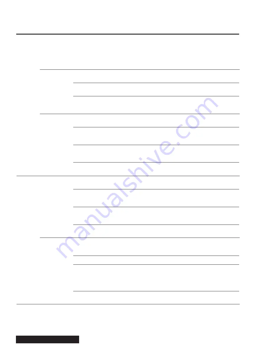
Test Procedure/Corrective Action
If the feed roller does not move when the feed control bar is in the reverse feed position, and
all the previous checks show that the system is functioning properly, install a pressure gauge
in the system. The main control valve has a quick connect port located by the panic bar spool
which will allow for connection to a pressure gauge. If the feed wheel is in a bind, the pressure
should read 2,500 psi (172.4 bar). Another option to confirm hydraulic flow to the feed wheel is to
install a pressure gauge in the hose going to the T (or B) port of the EFC valve. With the control
bar and valve in the reverse feed position, this should read approximately 2,500 psi (172.4 bar).
Material can build up around the feed roller, or wedge between the feed roller assembly and
feed box causing a jam.
With the unit running, cycle the feed control bar from forward to reverse several times. This may
sometimes “back flush” jammed material or debris and allow the unit to continue operating normally.
With the unit locked out and tagged out according to instructions previously mentioned in the
manual, try moving the feed roller slightly back and forth. If the system is jammed, refer to the
Clearing Feed System and Discharge Chute section of the manual.
At times, all systems may check out fine, but material may not move forward. The feed roller
may climb the limbs and pull them slightly but will stall or spin on the material.
The feed opening is 12” high by 17” wide (30.5 cm high by 43.2 cm wide). Anything wider than
this will not advance forward. Remove the material from the chipper, and proceed to cut the
material to a dimension which will fit in the opening.
Some materials like cedar and cypress can be very resilient or slippery preventing the feed wheel
from gripping and pulling it through. Use the lift cylinder for down pressure to gain better traction
in order to advance the material forward.
If the system is jammed, refer to the Clearing Feed System and Discharge Chute section of the
manual.
The lift cylinder can be used to hydraulically lift the feed roller assembly open, or it can be used
to apply down pressure to large piles of debris for traction.
When the panic bar is tripped, it will mechanically deflect a cam attached to the first spool of the
main control valve. This will in turn shift the valve to dump oil directly to tank. Reset panic bar
by returning the red valve handle to neutral state.
The cylinder needs both pressure and flow to actuate in/out. Install a gauge on the quick con
-
nection on the main control valve, and measure the pressure while toggling the cylinder rise/
lower lever. At full rise, and at full lower, the pressure should read around 1,160 psi (80 bar).
Material blocking the feed roller assembly from traveling up and down. If the system is jammed,
refer to the Clearing Feed System and Discharge Chute section of the manual.
The lift cylinder can be hydraulically actuated up or down. By releasing the lift cylinder lever, a
spool in the main control valve will shift to neutral. The cylinder will lose pressure allowing the
feed roller assembly to descend to rest.
Check linkages to ensure the cylinder lift lever returns to neutral.
Electrical problem if the cylinder stays up when the machine is off. Check the connector going
to the holding valve (labeled H). Using a test light, or multimeter, probe the pins to ensure that
power is not delivered to the solenoid. If the ground signal wire is loose and touching metal, it
can cause false trips. This valve is an integral part of the advance system recovery and will only
energize for a short period of time (no more than five seconds at a time).
A jam could cause the cylinder to stay up even in machine off state? If the system is jammed,
refer to the Clearing Feed System and Discharge Chute section of the manual.
Possible Cause
Feed roller is
jammed.
Material will not
move forward.
Lift cylinder does
not operate up/
down.
Lift cylinder is
stuck (at any
point in the
range of stroke).
Symptom
Unit will not
feed (cont.)
Lift cylinder
malfunction.
Содержание DRM 12
Страница 3: ......
Страница 7: ...2 Section 1 Introduction...
Страница 17: ...12 Section 3 Safety Rear View Top View Bottom View 12 5 22 19 10 23 10 17 30 20 3 2 30...
Страница 18: ...Section 3 Safety 13 4 8 7 2 3 970116658 1 6 5...
Страница 19: ...14 Section 3 Safety 970116649 970116652 12 14 13 10 11 9...
Страница 21: ...16 Section 3 Safety D G G D 25 26 24 27 23 22...
Страница 22: ...Section 3 Safety 17 970137595 3X 30 31 28 29...
Страница 23: ...18 Section 3 Safety...
Страница 41: ...36 Section 6 Care of the Unit...
Страница 62: ...Appendix...
Страница 63: ......
Страница 79: ...16 Appendix Glossary...
Страница 83: ...Appendix Daily Preoperational Checklist...
Страница 85: ...Appendix Preventive Maintenance and Inspection Checklist...
Страница 88: ......
Страница 89: ......
Страница 91: ......
Страница 93: ......
Страница 96: ...07 13 970413443 A 2A PAGE 1 OF 2 ASSEMBLY FEED SYSTEM HYDRAULIC LIFT DRM 12...
Страница 99: ...07 13 970413407 A 3A PAGE 1 OF 4 ASSEMBLY FEED CONTROL HYDRAULIC LIFT DRM 12...
Страница 103: ...08 13 970485929 A 4A PAGE 1 OF 3 ASSEMBLY HAND CRANK CHUTE ROTATION DRUM CHIPPER...
Страница 108: ...07 13 970413409 A 5A PAGE 1 OF 3 ASSEMBLY POWER SYSTEM KUBOTA 67 HP 74 HP 99 HP DIESEL DRM 12...
Страница 113: ...07 13 970413438 A 6A PAGE 1 OF 4 FINAL ASSEMBLY DRM 12...
Страница 117: ......
Страница 118: ......
Страница 119: ......
Страница 120: ......
Страница 121: ......
Страница 122: ......
Страница 123: ......
Страница 124: ......
Страница 125: ......
Страница 127: ......
Страница 128: ......
Страница 129: ......
Страница 138: ...79A PAGE 1 OF 3 05 13 970457633 A ASSEMBLY FUEL SYSTEM DRM12 CFD1217...


